Mitsubishi Canter (FE, FG). Manual - part 55
9 Technical data
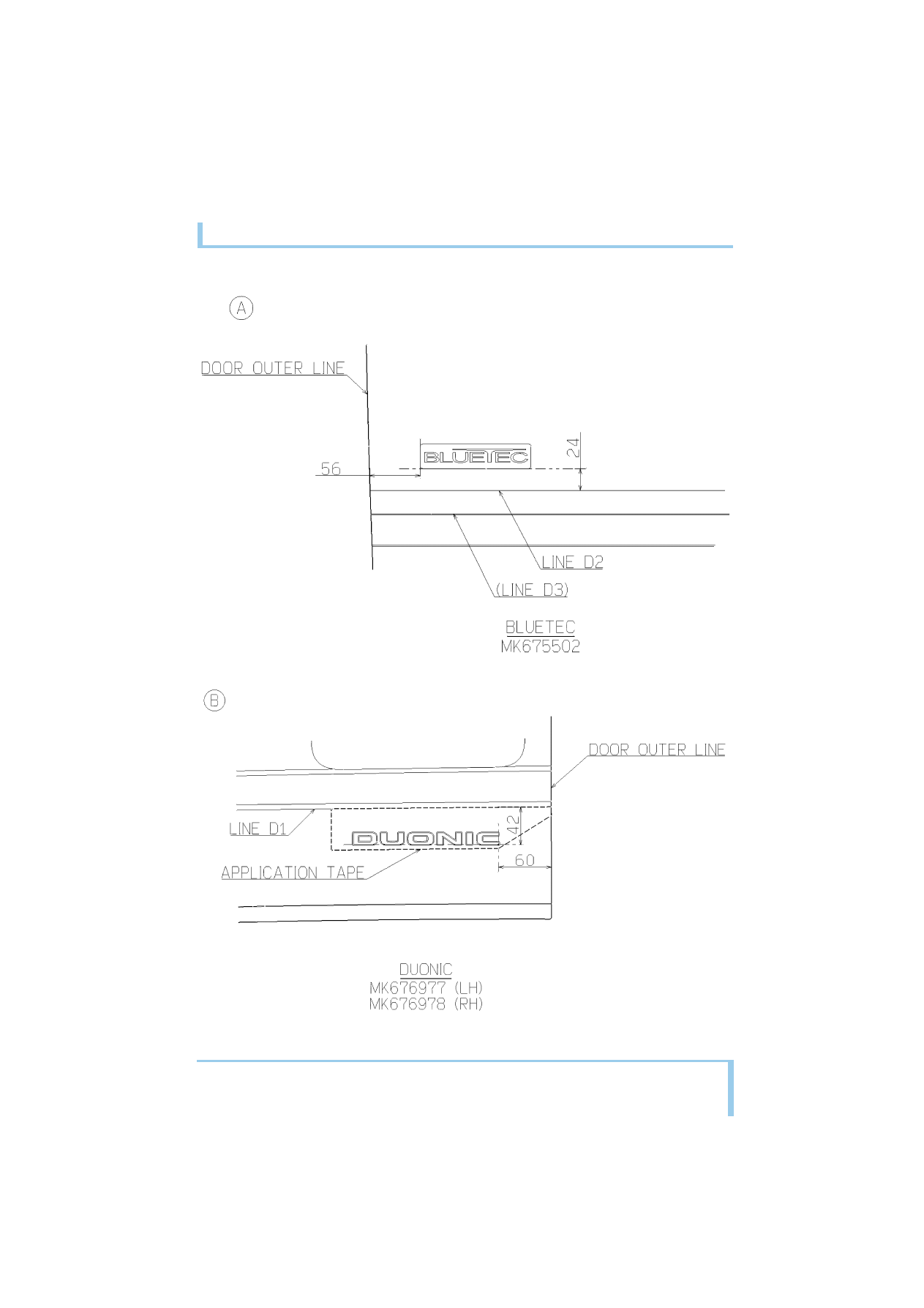
9.15 Labels and marks
220
MITSUBISHI FUSO body/equipment mounting directives for FE, FG Issue date: 06. 07. 2012
!
Only print out complete sections from the current version
i
|
|
|
9 Technical data 9.15 Labels and marks 220 MITSUBISHI FUSO body/equipment mounting directives for FE, FG Issue date: 06. 07. 2012 ! Only print out complete sections from the current version i |