Mitsubishi Canter (FE, FG). Manual - part 21


  Index      Mitsubishi     Mitsubishi Canter (FE, FG) - service manual 2013 year


Search            


Content   ..  19  20  21  22   ..


Mitsubishi Canter (FE, FG). Manual - part 21


84

6 Modifications to the basic vehicle 

6.3 Drilling work on the vehicle frame

MITSUBISHI FUSO body/equipment mounting directives for FE, FG  Issue date: 06. 07. 2012

!

 Only print out complete sections from the current version

i

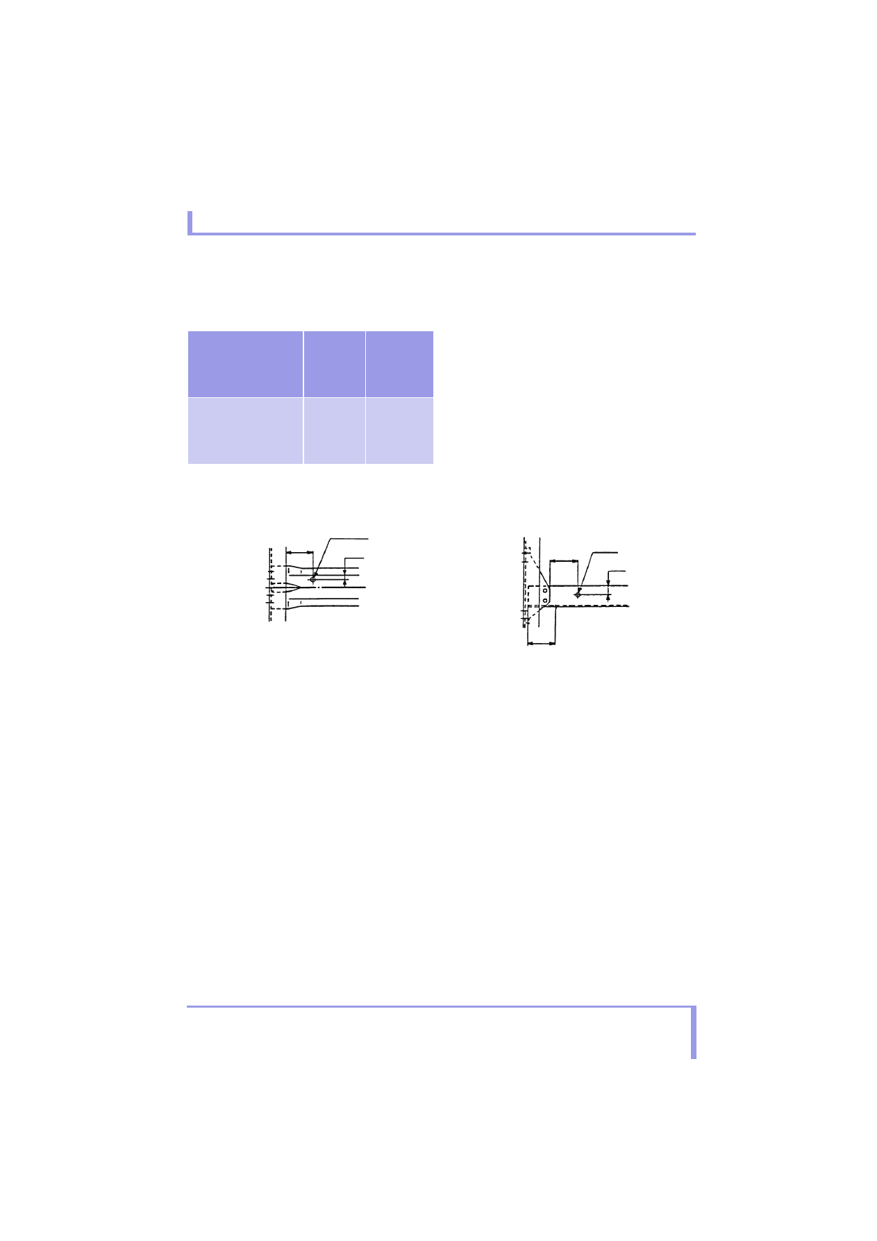
Drilling work on the crossmembers

• The holes and distances between the holes should 

conform to the values specified in the chart below.

Note*: Maintain the dimensions of previously drilled 

holes.

• Holes should be more than 100 mm {3.94 in.} away 

from the end of the side rail flange or the end of the 
gusset.

• Holes in the web of the channel type crossmember 

should be 50 mm {1.97 in.} min. from the end of the 
crossmember. (Refer to Fig. 2)

• Holes in the flange should be more than 25 mm 

{0.98 in.} from the end.

• Holes should be drilled more than 20 mm {0.79 in.} 

from the curved part of the flange.

Crossmember type

Hole 
diameter

Center-to-
center 
distance of 
holes

• Alligator type

(see Fig. 1)

• Channel type

(see Fig. 2)

9 mm 
{0.35 in.} 
max.

30 mm {1.18 
in.}* min.

Alligator type

Fig. 1

1

2

3

4

5

6

7

Channel type

Fig. 2

1

100 mm {3.94 in.} min

2

DIA 9 mm {0.35 in.} max

3

25 mm {0.98 in.} min

4

100 mm {3.94 in.} min

5

DIA 9 mm {0.35 in.} max

6

25 mm {0.98 in.} min

7

50 mm {1.97 in.} min (Web surface)

85

6 Modifications to the basic vehicle 

6.4 Welding work on the vehicle frame

MITSUBISHI FUSO body/equipment mounting directives for FE, FG  Issue date: 06. 07. 2012

!

 Only print out complete sections from the current version

i

6.4 Welding work on the vehicle frame

Welding anything onto chassis frame is prohibited in 
principle, as doing so increases the risk of cracks in 
the member. For detailed instructions about rear body 
mounting, see 7.2 “Mounting frame” 

컄 page 112.

i

Further information on welded connections can be 
found in Section 5 "Damage prevention" 
컄 page 65.

86

6 Modifications to the basic vehicle 

6.5 Reinforcements

MITSUBISHI FUSO body/equipment mounting directives for FE, FG  Issue date: 06. 07. 2012

!

 Only print out complete sections from the current version

i

6.5 Reinforcements

Reinforcement for a cab-back-mounted crane

Adding a stiffener to the outside of a side rail generally 
has no reinforcing effect, as the stiffener (or a local 
reinforcement) will create a sudden change in rigidity 
in the frame, which is likely to cause cracks to develop 
in the frame. However, frame reinforcement is 
indispensable around the crane mounting area where 
stress concentrates during crane operation; follow the 
instructions below when performing such frame 
reinforcement work:

• Any of the ends of outer stiffeners should not be 

aligned with any of the ends of a sub side rail inside 
the side rail.

• Any of the ends of outer stiffeners should not be 

aligned with any stress concentration point such as 
the back of the cab, an area neighboring a spring 
hanger, and cross member ends. If it is 
unavoidable to locate a stiffener end close to a 
spring hanger, avoid aligning the ends of upper and 
lower stiffeners.

• Cut any end of an outer stiffener at an angle of 

more than 45 degrees, not squarely.

• Fasten outer stiffeners to side rails by riveting or 

bolting on the web surface.

• Use 10 mm {0.39 in.}-diameter rivets and M10 

bolts for fastening. Use a riveting machine for 
riveting.

Tightening torque

Unit: N·m {ft.lbs, kgf·m}

Do not use ground bolts for fastening outer 
stiffeners. Mount the DEF tank bracket (plastic) 
with bolts tightened to a torque of 21 to 31 N·m {15 
to 23 ft.lbs, 1 to 3.2 kgf·m}.

• When re-riveting, do not use a rivet of the same 

diameter as the removed rivet in the same place. It 
is permitted to re-rivet with an 11 mm (0.43 in.) 
diameter rivet in place of a removed 10 mm 
(0.39 in.) diameter rivet after enlarging the hole 
correspondingly, provided the distance from the 
end of the outer stiffener is at least 25 mm 
(0.98 in.) from the edge of the rivet hole.

• Always fasten the front and rear ends of any outer 

stiffener.

• Stiffeners must be fastened especially securely 

around the No.2 cross member.

• The spacing between rivets or bolts should be no 

more than 200 mm (7.87 in.). The spacing must be 
closer near the ends of an outer stiffener.

• A channel-section stiffener, if inferior in 

dimensional accuracy, will create a gap at its 
flanges when installed on a side rail and may cause 
problems. Instead, use two L-section stiffeners on 
the top and bottom sides of the side rail.

• To ensure that the seating surfaces of bolts and 

nuts function properly, do not make outer stiffener 
mounting holes any larger than 11 mm {0.43 in.} in 
diameter. Slotting holes must not be used.

• If any chassis part has to be mounted astride an 

outer stiffener, create a gap in height with spacers 
{approx. 25 x 160 mm {0.98 x 6.3 in.}} equal to the 
outer stiffener added between them. Do not use 
existing plain washers for this purpose.

• Do not use bolts at the four corners outside the 

cross member/transmission mount to fasten outer 
stiffeners.

A

Name

Tightening torque

Bolt M10
Flange bolt 10T

88 to 105

{65 to 80, 9 to 11}

Nut M10
Flange nut 6T

Always fasten the front and rear ends of the outer stiffener.

Securely fasten the stiffener around the No. 2 cross member.

If stiffener ends are unavoidably located close to the spring hanger, 

avoid aligning the ends of the upper and lower stiffeners with each other.

87

6 Modifications to the basic vehicle 

6.5 Reinforcements

MITSUBISHI FUSO body/equipment mounting directives for FE, FG  Issue date: 06. 07. 2012

!

 Only print out complete sections from the current version

i

6.5.1

Others

Never drill or grind any notches in the side rail, 
crossmember flange, or crossmember gusset.

1

2

3

1

Side  rail

2

Crossmember gusset

3

Crossmember


Content   ..  19  20  21  22   ..