Mitsubishi Canter (FE, FG). Manual - part 8


  Index      Mitsubishi     Mitsubishi Canter (FE, FG) - service manual 2013 year


Search            


Content   ..  6  7  8  9   ..


Mitsubishi Canter (FE, FG). Manual - part 8


32

3 Planning of bodies 

3.8 Duonic

®

i

MITSUBISHI FUSO body/equipment mounting directives for FE, FG  Issue date: 06. 07. 2012

!

 Only print out complete sections from the current version

3.8.3

Initialization of DUONIC

®

 system

Initializing the DUONIC

® 

system stores the GSU (gear 

shift unit) gear position, road surface grade zero point 
correction value, clutch fill time learning value and 
clutch torque learning value in the memory of the TCU. 
It must be performed after ANY type of transmission-
related service.

If any abnormality occurs during normal running, it 
may be cleared by initialization. Some kinds of body 
equipment work to the vehicle can cause an error in 
road surface grade recognition. To prevent this, be 
sure to initialize the DUONIC

®

 system under the 

following conditions after body equipment work.

Conditions for initialization

Check the following before initialization.

(a) The engine electronic control unit and 

DUONIC

®

 electronic control unit (TCU) are 

finished with flashing (programming) and 
coding (in case of a change in tire size or final 
ratio). For details, contact a MITSUBISHI FUSO 
service center.

(b) To compute the road grade zero point 

correction value, make sure that the vehicle is 
in the following state:

• Standing still, brake released, on a flat surface 

such that the vehicle remains stationary 
without drifting forward or backward

• Equipped with specified wheels with the tires 

filled to correct pressures.

• Cab tilt locked (a G sensor is provided in the 

cab.)

(c) For learning the clutch torque, units powered by 

the engine, such as the following, must be 
stopped:

• Air conditioner
• Load for equipment (compressor for refrig-

erator, etc.)

• Exhaust  brake

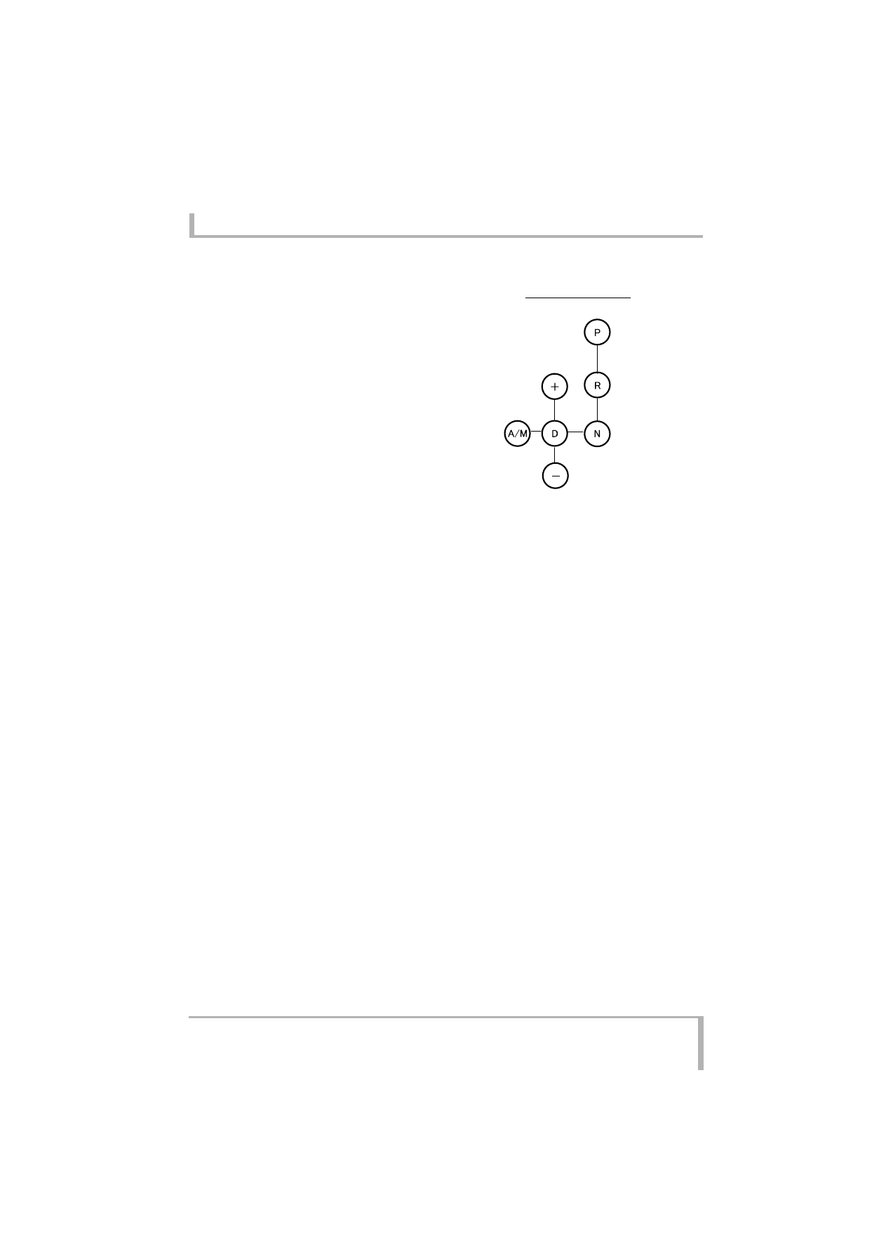
Change lever pattern

33

3 Planning of bodies 

3.8 Duonic

®

i

MITSUBISHI FUSO body/equipment mounting directives for FE, FG  Issue date: 06. 07. 2012

!

 Only print out complete sections from the current version

Initialization procedure

(a) In case of failure of initialization
• Repeat the initialization procedure from the 

start.

• If initialization still goes wrong, there may be a 

problem with the hardware. Check the 
transmission (including gears, clutch, 
associated parts, valve body and GSU) and their 
connections.

• If the indicator shows from [2] to [R] blinking, 

move the vehicle once, then perform the initial-
ization procedure. The problem may be 
resolved.

Operation

Resultant status

Remarks

• Hold vehicle on flat surface. (3.8.3 

(b))

• Turn key ON.
• Stop  engine.
• Switch off air conditioner, 

equipment load and exhaust 
brake. (3.8.3 (c))

• Accelerator ON (50% or more)
• Foot brake ON
• Change lever

D → (hold for approx. 1 second) 
→ Hold A/M

• Parking brake

ON → (hold for approx. 1 second) 
→ OFF → (hold for approx. 1 
second) → ON (pull a little hard)

[Initialize mode standby status] is 
established and indicator shows [1] 
blinking.

[To clear initialize mode 
standby status to return to 
normal mode], release 
parking brake or turn key OFF 
and hold it OFF for 1 second.

From initialize mode standby status,

• Turn accelerator OFF
• Place change lever to [P].

Then, start engine.

•  With progress of initialization, 

indicator shows [2-3-4-5-N] 
blinking in that order.

• If initialization goes wrong, [R] is 

shown blinking.

Even if foot brake is released 
after engine is started, 
initialize mode remains, but 
for safety, foot brake should 
be kept ON.

(Status by indication)

[2] Detection of GSU gear position in 

progress

[3] Clutch warming up + road grade 

zero point compensation in 
progress

[4] Clutch fill time learning in 

progress

[5] Clutch torque learning in progress
[N] Initialize completed
[R] Initialize failed

Release parking brake or turn key 
OFF and hold it in that state for 1 
second.

Mode is returned to normal.

34

3 Planning of bodies 

3.8 Duonic

®

i

MITSUBISHI FUSO body/equipment mounting directives for FE, FG  Issue date: 06. 07. 2012

!

 Only print out complete sections from the current version

3.8.4

Resetting of initial DUONIC

®

 settings

The DUONIC

®

 system has a reset function for 

restoring the initially set GSU gear position, road 
grade zero point compensation value, clutch fill time 
learning value and clutch torque learning value to the 
pre-initialization status. (This is a back-up function 
used in case any initial settings are found to be 
abnormal and affect the vehicle operation; it is not 
normally used.)

Resetting procedure

3.8.5

Cautions during body equipment work on 
DUONIC

®

 vehicle

The DUONIC

®

 transmission and control system is a 

computerized and electronically controlled system; 
mishandling could cause system errors and in the 
worst case, breakdown of the computer itself. 
Therefore, body equipment work on the vehicle should 
be carried out with following the precautions given 
below.

General handling precautions

• Be sure not to change the tire size, final ratio, and 

speedometer gear ratio of a DUONIC

®

 vehicle.

• Be sure not to alter DUONIC

®

-associated devices, 

sensors, harnesses and connectors in any way.

• Before disconnecting DUONIC

®

-associated 

connectors, set the starter switch of the vehicle to 
OFF. Before turning the starter switch ON, 
reconnect the disconnected connectors.
If DUONIC

®

-associated device connectors are 

disconnected while power is supplied to the TCU, a 
warning lamp will light or the system may lose 
functionality.

• Before painting the transmission body, mask 

electric parts, harnesses, connectors, breathers, 
oil cooler pipe joints and other parts which should 
be covered.
Furthermore, mask wrong fluid/oil supply 
preventive labels (ATF ONLY, GEAR OIL ONLY) 
attached near to appropriate fluid/oil plugs so that 
they are not covered with paint.

• After completing the body equipment work on the 

vehicle, make sure that the vehicle runs without 
any problem. 

Operation

Status

Remarks

• Turn key ON.
• Stop  engine.
• Accelerator ON (50% or more)
• Foot brake ON
• Change lever

D → (hold approx. 1 second) → 
Hold A/M

• Parking brake

ON → (hold approx. 1 second) → 
OFF → (hold approx. 1 second) 
→ ON

[Initialize mode standby status] is 
established and indicator shows 
[1] blinking.

[To clear initialize mode standby 
status to return to normal mode], 
release parking brake or turn key 
OFF and hold it OFF for 1 second.

From initialize mode standby status, 
place change lever to [–].

With resetting completed, 
indicator [6] blinks.

Release parking brake, or hold key 
OFF for 1 second.

Mode returns to normal.

35

3 Planning of bodies 

3.8 Duonic

®

i

MITSUBISHI FUSO body/equipment mounting directives for FE, FG  Issue date: 06. 07. 2012

!

 Only print out complete sections from the current version

3.8.6

Power take-off for DUONIC

®

 (mechanical 

automatic transmission)-equipped 
vehicle

The vehicle cannot be run while the power take-off is 
in operation.

Vacuum-type power take-off operation procedure

• With the engine running, place the shift lever into 

the P position (or N position).

• Set the power take-off main switch in the cab to 

ON.

• The indicator lamp 

 lights to indicate that the 

power take-off is in preparation.

• With the indicator lamp 

 on, the power take-off 

can be used.

• To clear this status, set the power take-off main 

switch in the cab to OFF. The indicator lamp 


goes off and the indicator lamp 

 goes on. The 

power take-off is being released.
The indicator lamp 

 goes off to indicate that the 

power take-off has been released.

Cable type power take-off operation procedure

• With the engine running, place the shift lever to the 

P position (or N position).

• Set the power take-off main switch in the cab to 

ON.

• The indicator lamp 

 lights.

• Connect the power take-off by means of the power 

take-off lever or damp lever.

• The indicator 

 goes on to indicate that the 

power take-off is operational.

• To release the power take-off, set the power take-

off main switch in the cab to OFF. The indicator 
lamp 

 goes off and the indicator lamp 

 goes 

on to indicate that the power take-off is ready to be 
released.
Release the power take-off by means of the power 
take-off lever or damp lever. The indicator lamp 

 goes off to indicate that the power take-off has 

been released.

Cautions

• The indicator lamp 

 may not show, depending 

on the sequence, operating speed or device 
response speed, which is not an abnormality.

• If the shift lever is in a position other than P or N, 

the power take-off is not connected even if the 
power take-off switch is turned ON. In the case 
where the shift lever is in a position other than P or 
N or the power take-off switch is turned to ON 
during running, the buzzer sounds and the warning 
indication of 

 appears on the meter. Turning 

the power take-off switch to OFF restores the state 
to normal.

• If the shift lever is placed into a position other than 

P or N or the power take-off switch is turned to ON 
when the power take-off is working, the buzzer 
sounds and the warning indication of 

 appears 

on the meter.


Content   ..  6  7  8  9   ..