Mitsubishi 380. Manual - part 971


  Index      Mitsubishi     Mitsubishi 380 - service repair manual 2005 year


Search            


Content   ..  969  970  971  972   ..


Mitsubishi 380. Manual - part 971


TRANSMISSION ASSEMBLY

MANUAL TRANSMISSION

22A-9

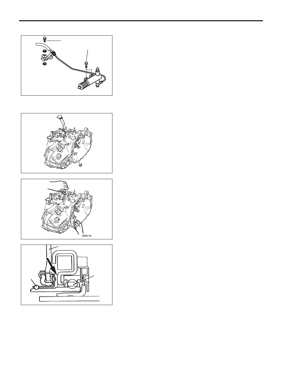
<<B>> CLUTCH RELEASE CYLINDER

09DB030A

18 ± 3.0 N·m

18 ± 3.0 N·m

1. Remove the clutch release cylinder without disconnecting 

the fluid line and secure to vehicle chassis.

.

<<C>> RELEASE BEARING

09DB025A

1. Remove the access hole covers from th top and bottom of 

the clutch housing.

2. Push the clutch cylinder end of the release fork so that the 

release bearing pushes against the diaphram spring.

09DB026A

09DB027A

DIAPHRAGM SPRING

RELEASE

BEARING

RING

Place

screwdriver

here

3. Insert a flat blade screwdriver in both top and bottom access 

hole in the clutch housing, between the release bearing and 
the diaphram spring. Simultaneously turn both srewdrivers 
through 90 to diengage the release bearing.

.

TRANSMISSION ASSEMBLY

MANUAL TRANSMISSION

22A-10

<<D>> TRANSMISSION MOUNT BRACKET

09DB035A

CHASSIS BRACKET

MOUNT

1. Jack up the transmission assembly gently with garage jack 

and then remove the transmission mount bracket through 
bolt. Mount assembly remains attached to transmission until 
removed from vehicle.

.

<<E>> ENGINE ASSEMBLY SUPPORTING

AC306198

MB991527

MB991454

MB991895

AB

1. Set up the special tool to the vehicle to support the engine 

assembly.

.

<<F>> TIE ROD END/LOWER ARM BALL JOINT REMOVAL

AC208247AC

CORD

BOLT

MB991897

NUT

BALL JOINT

1. Set up the special tool to the vehicle to support the engine 

assembly.

.

<<G>> DRIVE SHAFT REMOVAL

AC100141AL

TRANSAXLE

PTJ ASSEMBLY

PRY BAR

1. Insert a pry bar between the transmission case and the drive 

shaft to remove the shaft from trnsmission housing.

09DB028A

MB991460

TRANSMISSION ASSEMBLY

MANUAL TRANSMISSION

22A-11

2. To prevent foreign material from entering the transmission 

case, insert a suitable plug into the drive shaft openings.

3. Suspend the RH drive shaft with wire so that there are no 

sharp bends in any of the joints.

INSTALLATION SERVICE POINT

.

>>A<< TRANSMISSION MOUNT STOPPER INSTALLATION

09DB029A

ENGINE SIDE

TRANSAXLE 

MOUNTING 

STOPPER

1. Install the transmission mount stopper so that the arrow 

points upward as shown in illustration. Ensure stoppers are 
installed onto mount correctly prior to fitment and do not 
dislodge during transmission installation.

TRANSMISSION ASSEMBLY

MANUAL TRANSMISSION

22A-12


Content   ..  969  970  971  972   ..