Mitsubishi 380. Manual - part 961


  Index      Mitsubishi     Mitsubishi 380 - service repair manual 2005 year


Search            


Content   ..  959  960  961  962   ..


Mitsubishi 380. Manual - part 961


ANTI-LOCK BRAKING SYSTEM (ABS) DIAGNOSIS

ANTI-LOCK BRAKING SYSTEM (ABS)

35B-69

DTC U1073: CAN-Bus off

CAUTION

• If DTC U1073 is set in the ABS-ECU, always 

diagnose the CAN main bus line. If there is 
any fault in the CAN bus lines, an incorrect 
DTC may be set.

• Whenever the ECU is replaced, ensure that 

the communication circuit is normal.

.

TROUBLE JUDGMENT

This code is stored when the ABS-ECU has ceased 
the CAN communication (bus off). Then, if a penalty 
mode is entered after approximately five minutes, the 
regular data transmission from the ABS-ECU will be 
cancelled.

.

TROUBLESHOOTING HINTS (The most 
likely causes for these DTCs are to set 
are:)

• Damaged wiring harness or connector

• Malfunction of the hydraulic unit (integrated with 

ABS-ECU)

Circuit drawings

• Refer to circuit diagrams GROUP-

90

• Refer to configuration diagrams GROUP-

80

.

DIAGNOSIS

Required Special Tools:

• MB991958: Diagnostic Tool (MUT-III Sub Assembly)

• MB991824: Vehicle Communication Interface (V.C.I.)

• MB991827: MUT-III USB Cable

• MB991910: MUT-III Main Harness A

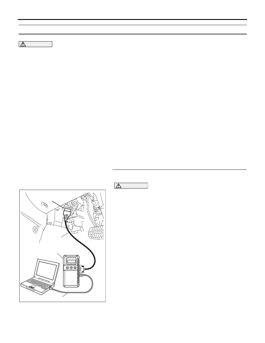
STEP 1. Using diagnostic tool MB991958, diagnose the 
CAN bus line.

CAUTION

To prevent damage to diagnostic tool MB991958, always 
turn the ignition switch to the "LOCK" (OFF) position 
before connecting or disconnecting diagnostic tool 
MB991958.
(1) Connect diagnostic tool MB991958 to the data link 

connector.

(2) Turn the ignition switch to the "ON" position.
(3) Diagnose the CAN bus line.
(4) Turn the ignition switch to the "LOCK" (OFF) position.

Q: Is the CAN bus line found to be normal?

YES : Go to Step 2.
NO :  Repair the CAN bus line (Refer to GROUP 54C, 

Diagnosis 

P.54C-15

). Then go to Step 2.

00DB076A

MB991910

DATA LINK

CONNECTOR

MB991824

MB991827

ANTI-LOCK BRAKING SYSTEM (ABS) DIAGNOSIS

ANTI-LOCK BRAKING SYSTEM (ABS)

35B-70

STEP 2. Recheck for diagnostic trouble code.
Check again if the DTC is set.
(1) Turn the ignition switch to the "ON" position.
(2) Erase the DTC.
(3) Turn the ignition switch to the "LOCK" (OFF) position.
(4) Turn the ignition switch to the "ON" position.
(5) Check if the DTC is set.
(6) Turn the ignition switch to the "LOCK" (OFF) position.

Q: Is DTC U1073 set?

YES : Replace the ABS-ECU. Then go to Step 3.
NO :  It can be assumed that this malfunction is intermittent. 

Refer to GROUP 00, How to Use 
Troubleshooting/Inspection Service Points 

− How to 

Cope with Intermittent Malfunction 

P.00-14

.

STEP 3. Recheck for diagnostic trouble code.
Check again if the DTC is set.
(1) Turn the ignition switch to the "ON" position.
(2) Erase the DTC.
(3) Turn the ignition switch to the "LOCK" (OFF) position.
(4) Turn the ignition switch to the "ON" position.
(5) Check if the DTC is set.
(6) Turn the ignition switch to the "LOCK" (OFF) position.

Q: Is DTC U1073 set?

YES : Go to Step 1.
NO :  The procedure is complete.

00DB076A

MB991910

DATA LINK

CONNECTOR

MB991824

MB991827

00DB076A

MB991910

DATA LINK

CONNECTOR

MB991824

MB991827

ANTI-LOCK BRAKING SYSTEM (ABS) DIAGNOSIS

ANTI-LOCK BRAKING SYSTEM (ABS)

35B-71

SYMPTOM CHART

M1352011400619

CAUTION

During diagnosis, a DTC code associated with 
another system may be set when the ignition 
switch is turned on with connector(s) discon-
nected. On completion, confirm all systems for 
DTC code(s). If DTC code(s) are set, erase them 
all.

NOTE: If the ABS-8 ECU or the active wheel 
speed sensor are disconnected, or if the wiring is 
an open/ short circuit, the ABS 8 ECU will shut 
off power supply to the respective wheel speed 
sensor. All other wheel speed sensors will oper-
ate normally. To restore the power supply, the 
ignition switch must be turned to the "OFF" posi-
tion then to the "ON" position again.

NOTE: If steering movements are made when driv-
ing at high speed, or when driving on road surfaces 
with low frictional resistance, or when passing over 
bumps, the ABS may operate although sudden brak-
ing is not being applied. Because of this, when get-
ting information from the customer, check if the 
problem occurred while driving under such condi-
tions as these.

NOTE: During ABS operation, the brake pedal may 
vibrate a little or may not be able to be pressed. Such 
conditions are due to intermittent changes in hydrau-
lic pressure inside the brake line to prevent the 
wheels from locking. This is normal.

SYMPTOMS

INSPECTION 
PROCEDURE NO.

REFERENCE PAGE

Communication between the diagnostic tool and the 
ABS-ECU is not possible.

1

P.35B-72

Power supply circuit system

2

P.35B-74

When the ignition key is turned to "ON" (Engine 
stopped), the ABS warning light does not illuminate.

3

P.35B-79

The ABS warning light remains illuminated after the 
engine is started.

4

P.35B-79

Faulty ABS operation

5

P.35B-81

ANTI-LOCK BRAKING SYSTEM (ABS) DIAGNOSIS

ANTI-LOCK BRAKING SYSTEM (ABS)

35B-72

SYMPTOM PROCEDURES

INSPECTION PROCEDURE 1: Communication between Diagnostic Tool and the ABS-ECU is not 
possible.

.

TECHNICAL DESCRIPTION (COMMENT)

If the diagnostic tool (MUT-III Sub Assembly) cannot 
communicate with the ABS system, the CAN bus 
lines may be defective. If the ABS system does not 
work, the ABS-ECU or its power supply circuit may 
be defective. 

.

TROUBLESHOOTING HINTS (The most 
likely causes for this case:)

• Damaged wiring harness or connector

• Malfunction of the hydraulic unit (Integrated with 

ABS-ECU)

Circuit drawings

• Refer to circuit diagrams GROUP-

90

• Refer to configuration diagrams GROUP-

80

• Refer to component locations GROUP-

70

.

DIAGNOSIS

Required Special Tools:

• MB991958: Diagnostic Tool (MUT-III Sub Assembly)

• MB991824: Vehicle Communication Interface (V.C.I.)

• MB991827: MUT-III USB Cable

• MB991910: MUT-III Main Harness A

35DB090A

A


Content   ..  959  960  961  962   ..