Mitsubishi 380. Manual - part 960


  Index      Mitsubishi     Mitsubishi 380 - service repair manual 2005 year


Search            


Content   ..  958  959  960  961   ..


Mitsubishi 380. Manual - part 960


ANTI-LOCK BRAKING SYSTEM (ABS) DIAGNOSIS

ANTI-LOCK BRAKING SYSTEM (ABS)

35B-65

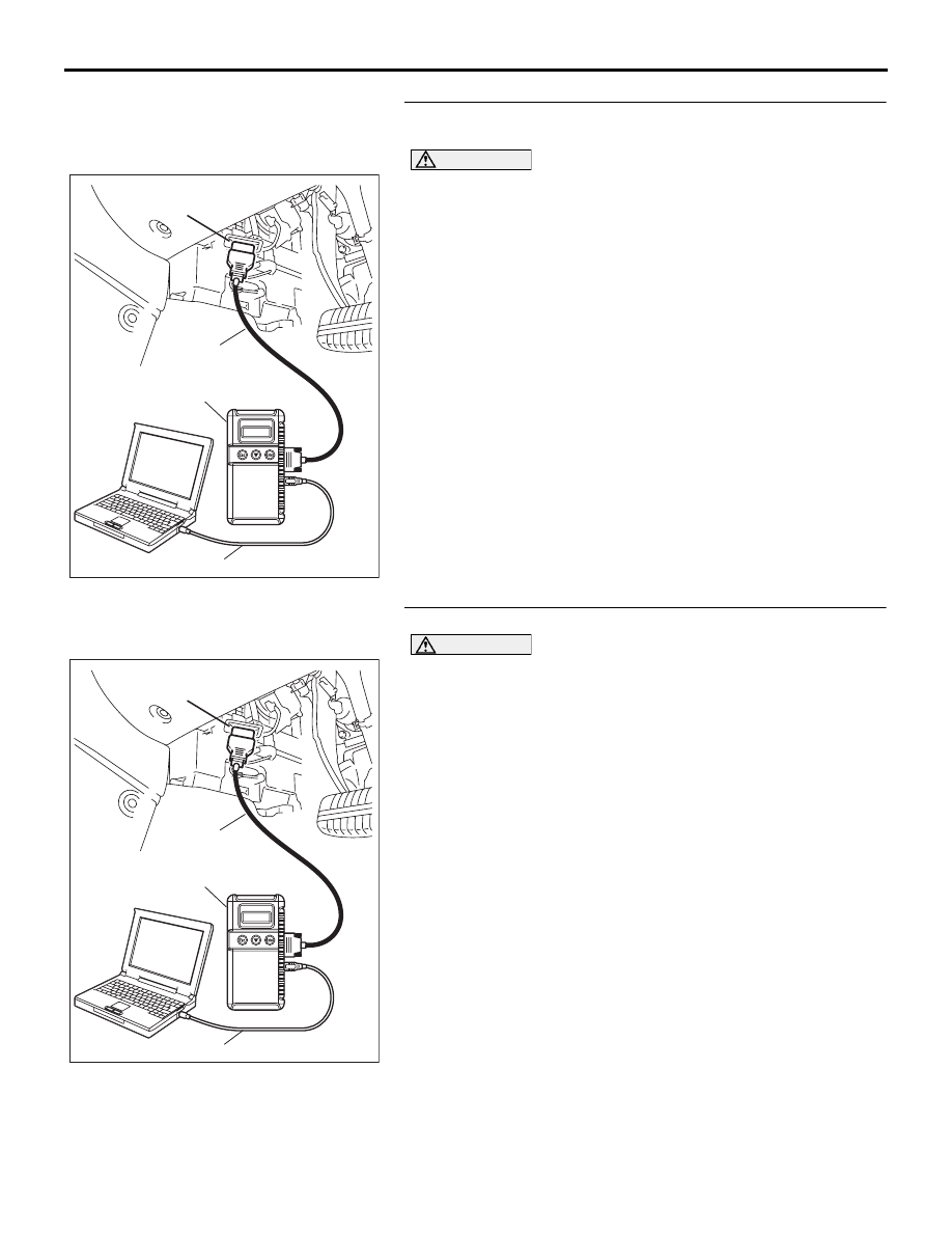
STEP 1. Using diagnostic tool MB991958, diagnose the 
CAN bus line.

CAUTION

To prevent damage to diagnostic tool MB991958, always 
turn the ignition switch to the "LOCK" (OFF) position 
before connecting or disconnecting diagnostic tool 
MB991958.
(1) Connect diagnostic tool MB991958 to the data link 

connector.

(2) Turn the ignition switch to the "ON" position.
(3) Diagnose the CAN bus line.
(4) Turn the ignition switch to the "LOCK" (OFF) position.

Q: Is the CAN bus line found to be normal?

YES : Go to Step 3.
NO :  Repair the CAN bus line (Refer to GROUP 54C, 

Diagnosis 

P.54C-15

).  Then go to Step 2.

STEP 2. Recheck for diagnostic trouble code.

CAUTION

To prevent damage to diagnostic tool MB991958, always 
turn the ignition switch to the "LOCK" (OFF) position 
before connecting or disconnecting diagnostic tool 
MB991958.
(1) Turn the ignition switch to the "ON" position.
(2) Erase the DTC.
(3) Turn the ignition switch to the "LOCK" (OFF) position.
(4) Turn the ignition switch to the "ON" position.
(5) Check if the DTC is set.
(6) Turn the ignition switch to the "LOCK" (OFF) position.

Q: Is DTC C1860 or C1861 set?

YES : Go to Step 3.
NO :  The procedure is complete.

00DB076A

MB991910

DATA LINK

CONNECTOR

MB991824

MB991827

00DB076A

MB991910

DATA LINK

CONNECTOR

MB991824

MB991827

ANTI-LOCK BRAKING SYSTEM (ABS) DIAGNOSIS

ANTI-LOCK BRAKING SYSTEM (ABS)

35B-66

STEP 3. Check the battery.
Check the battery (Refer to GROUP 54A, Battery test 

P.54A-6

).

Q: Is the battery in good condition?

YES : Go to Step 4.
NO :  Charge or replace the battery. Then go to Step 8.

STEP 4. Check the charging system.
Check the charging system (Refer to GROUP 16, Charging 
system diagnosis 

P.16-3

).

Q: Is the charging system in good condition?

YES : Go to Step 5.
NO :  Repair or replace the charging system component(s). 

Then go to Step 8.

STEP 5. Measure the voltage at ABS-ECU connector A-02.
(1) Disconnect the connector A-02, and use special tool 

Inspection Check Harness (MB991219) to probe the wiring 
harness-side connector.

NOTE: The special tool (Inspection test harness) 
MB991219 for connector pin contact pressure should be 
used. The test probe should never be forcibly inserted, as it 
may cause a defective contact.

(2) Turn the ignition switch to the "ON" position.
(3) Measure the voltage between terminal 18 and ground. It 

should be approximately 12 volts (battery positive voltage).

Q: Is the voltage approximately 12 volts (battery positive 

voltage)?
YES : 
Go to Step 7.
NO :  Go to Step 6.

35DB101A

CONNECTOR: A-02

HYDRAULIC UNIT

(WITH BUILT-IN ABS-ECU)

TEST 

HARNESS

(MB991219)

ANTI-LOCK BRAKING SYSTEM (ABS) DIAGNOSIS

ANTI-LOCK BRAKING SYSTEM (ABS)

35B-67

STEP 6. Check ABS-ECU connector A-02, junction block 
connectors C-214, C-215 and ignition switch connector 
C-318 for loose, corroded or damaged terminals, or 
terminals pushed back in the connector.

• ABS-ECU connector A-02

• Junction block connectors C-214 and C-215

• Ignition switch connector C-308

Q: Are the connectors and terminals in good condition?

YES : An open or short circuit may be present in the power 

supply line to the ABS-ECU. Repair the wiring 
harness between ABS-ECU connector A-02 terminal 
18 and ignition switch connector C-308 terminal 4. Go 
to Step 8.

NO :  Repair or replace the damaged component(s). Refer 

to GROUP 00E, Harness Connector Inspection 

P.00E-2

. Then go to Step 8.

16DB402A

A-02 (GR)

CONNECTOR: A-02 

A-02 HARNESS CONNECTOR:

35DB041A

CONNECTORS: C-214, C-215

C-215

1
3 4

2
6

5

C-214

6

1
7

2

9

8

10

3

5

12

11

4

1314

JUNCTION BLOCK

(FRONT VIEW)

35DB042A

CONNECTOR: C-308

C-308

2

5

4

1

6

3

ANTI-LOCK BRAKING SYSTEM (ABS) DIAGNOSIS

ANTI-LOCK BRAKING SYSTEM (ABS)

35B-68

STEP 7. Recheck for diagnostic trouble code.
Check again if the DTC is set.
(1) Turn the ignition switch to the "ON" position.
(2) Erase the DTC.
(3) Turn the ignition switch to the "LOCK" (OFF) position.
(4) Turn the ignition switch to the "ON" position.
(5) Check if the DTC is set.
(6) Turn the ignition switch to the "LOCK" (OFF) position.

Q: Is DTC C1860 or C1861 set?

YES : Replace the hydraulic unit (integrated with 

ABS-ECU). Then go to Step 8.

NO :  It can be assumed that this malfunction is intermittent. 

Refer to GROUP 00, How to Use 
Troubleshooting/Inspection Service Points 

− How to 

Cope with Intermittent Malfunction 

P.00-14

.

STEP 8. Recheck for diagnostic trouble code.
Check again if the DTC is set.
(1) Turn the ignition switch to the "ON" position.
(2) Erase the DTC.
(3) Turn the ignition switch to the "LOCK" (OFF) position.
(4) Turn the ignition switch to the "ON" position.
(5) Check if the DTC is set.
(6) Turn the ignition switch to the "LOCK" (OFF) position.

Q: Is DTC C1860 or C1861 set?

YES : Go to Step 1.
NO :  The procedure is complete.

00DB076A

MB991910

DATA LINK

CONNECTOR

MB991824

MB991827

00DB076A

MB991910

DATA LINK

CONNECTOR

MB991824

MB991827


Content   ..  958  959  960  961   ..