Mitsubishi 380. Manual - part 959
ANTI-LOCK BRAKING SYSTEM (ABS) DIAGNOSIS
ANTI-LOCK BRAKING SYSTEM (ABS)
35B-61
STEP 7. Recheck for diagnostic trouble code.
Check again if the DTC is set.
(1) Turn the ignition switch to the "ON" position.
(2) Erase the DTC.
(3) Turn the ignition switch to the "LOCK" (OFF) position.
(4) Turn the ignition switch to the "ON" position.
(5) Check if the DTC is set.
(6) Turn the ignition switch to the "LOCK" (OFF) position.
Q: Is DTC C1278 or C1279 set?
YES : Replace the hydraulic unit (integrated with
ABS-ECU). Then go to Step 8.
NO : It can be assumed that this malfunction is intermittent.
Refer to GROUP 00, How to Use
Troubleshooting/Inspection Service Points
− How to
Cope with Intermittent Malfunction
STEP 8. Recheck for diagnostic trouble code.
Check again if the DTC is set.
(1) Turn the ignition switch to the "ON" position.
(2) Erase the DTC.
(3) Turn the ignition switch to the "LOCK" (OFF) position.
(4) Turn the ignition switch to the "ON" position.
(5) Check if the DTC is set.
(6) Turn the ignition switch to the "LOCK" (OFF) position.
Q: Is DTC C1278 or C1279 set?
YES : Go to Step 1.
NO : The procedure is complete.
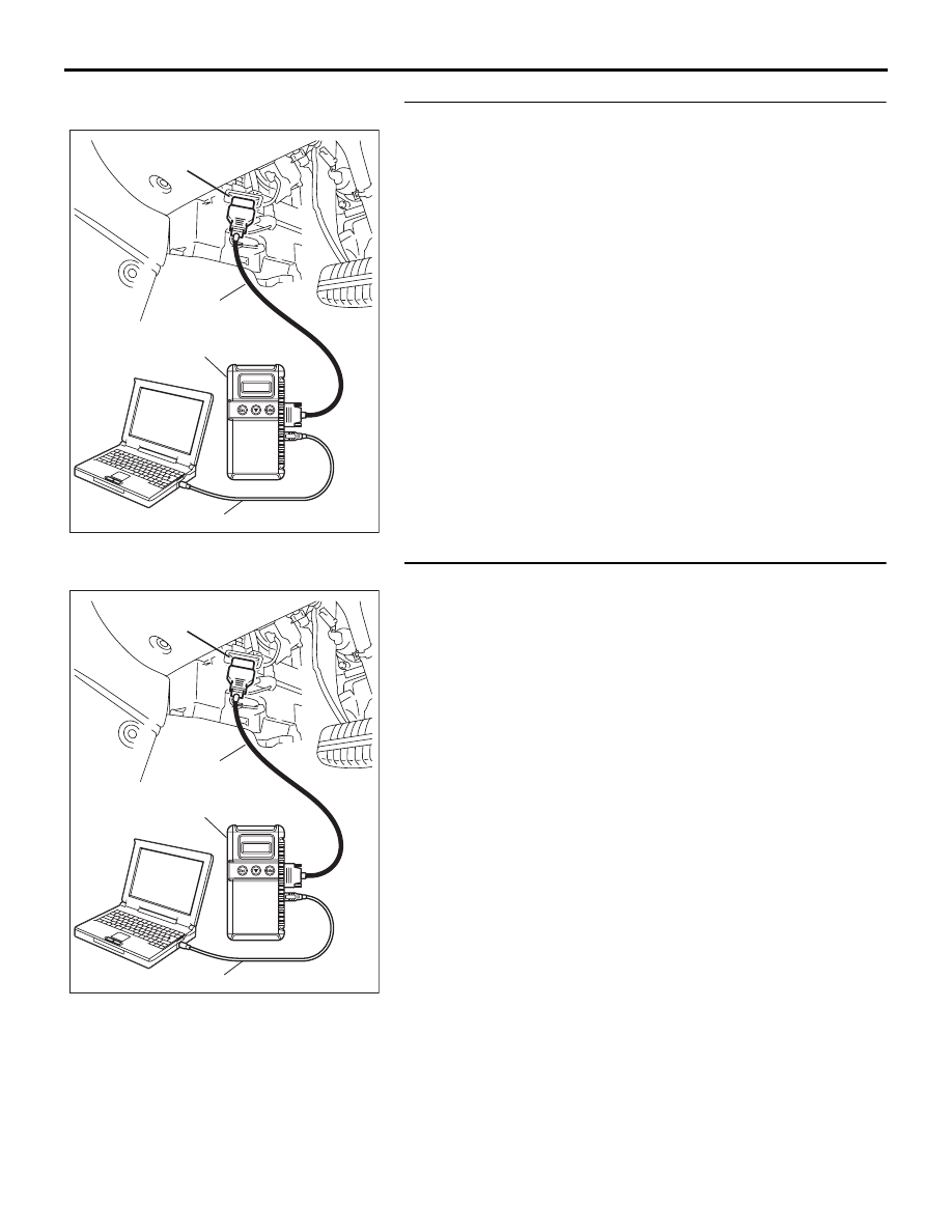
00DB076A
MB991910
DATA LINK
CONNECTOR
MB991824
MB991827
00DB076A
MB991910
DATA LINK
CONNECTOR
MB991824
MB991827