Mitsubishi 380. Manual - part 911
RADIO WITH CD PLAYER
CHASSIS ELECTRICAL
54A-178
SYMPTOM PROCEDURES
INSPECTION PROCEDURE 1: When Power Switch is Turned "ON," no Power is Available.
.
No sound from one speaker.
5
Noise
Noise is present while moving (AM).
6
Noise is present while moving (FM).
7
Sound mixed with noise, only at night
(AM).
10
Noise is overpowering both AM and FM. 11
Excessive noise on AM and FM.
12
Noise is detected with engine running.
13
Noise appears during vibration or
shocks.
14
Noise is present wile moving (FM) .
15
Constant noise.
16
Radio
No reception (AM).
17
Poor reception.
18
Distortion on AM and/or FM.
19
Distortion on FM only.
20
Auto select function inoperative, too few
automatic stations are selected.
21
Preset stations are erased.
22
CD player, CD auto
changer
CD can not be inserted.
23
No sound (CD only).
24
CD sound skips.
25
Sound quality is poor.
26
CD cannot be ejected.
27
SYMPTOM
INSPECTION
PROCEDURE
REFERENCE PAGE
52DB014A
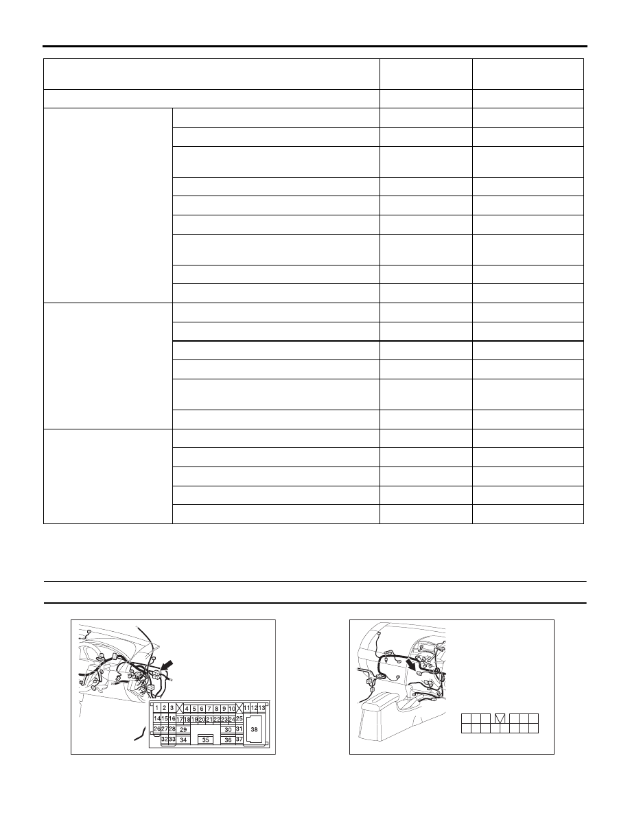
CONNECTOR: C-29
54DB041A
HARNESS SIDE
3
9
4
12
14
6
13
5
1110
8
2
7
1
CONNECTOR: C-111