Mitsubishi 380. Manual - part 905


  Index      Mitsubishi     Mitsubishi 380 - service repair manual 2005 year


Search            


Content   ..  903  904  905  906   ..


Mitsubishi 380. Manual - part 905


HEADLAMP AND POSITION LAMP ASSEMBLY

CHASSIS ELECTRICAL

54A-154

REMOVAL SERVICE POINT

.

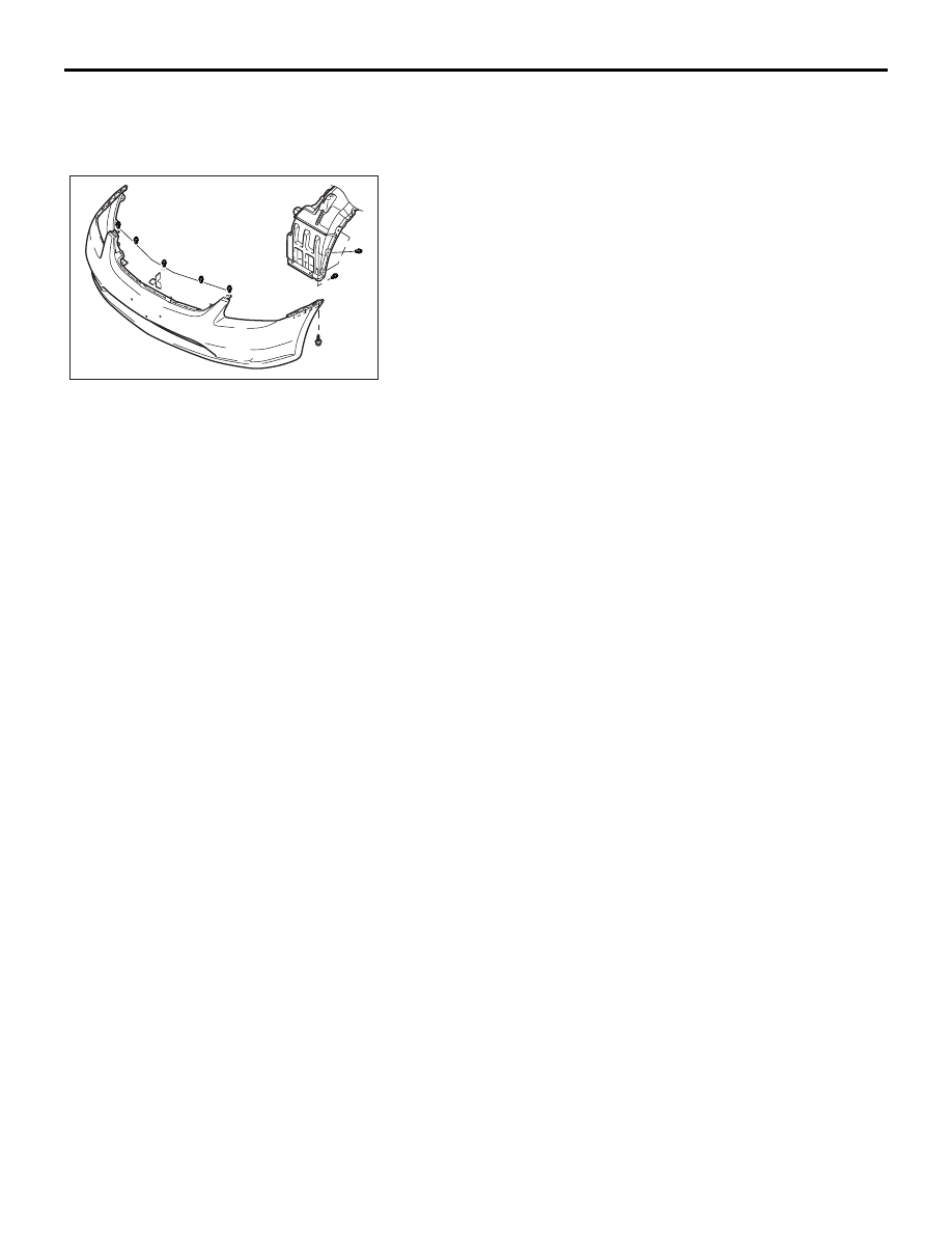
<<A>> HEADLAIGHT ASSEMBLY REMOVAL

Remove the front bumper mounting screw and clip.

16DB416A

FOG LAMP

CHASSIS ELECTRICAL

54A-155

FOG LAMP

FOG LAMP DIAGNOSIS

M1542000701366

The fog lamps are controlled by the Simplified Wiring 
System (SWS). For troubleshooting, refer to GROUP 
54B, SWS Diagnosis 

P.54B-57

.

ON-VEHICLE SERVICE

FOG LAMP AIMING

M1542001100472

PRE-AIMING INSTRUCTIONS

1. Inspect for badly rusted or faulty fog lamp assemblies.

2. These conditions must be corrected before a satisfactory 

adjustment can be made.

3. Inspect tyre inflation, and adjust if necessary.

4. If the fuel tank is not full, place a weight in the trunk of the 

vehicle to simulate weight of a full tank [0.8 kg per Litre].

5. There should be no other load in the vehicle other than 

driver or substituted weight of approximately 70 kg (150 
pounds) placed in driver's position.

6. Thoroughly clean the fog lamp lenses.

7. Measure centre of fog lamp lens, 41mm from anywhere of 

the outer edge of the lens as shown in the illustration below.

8. Place the vehicle on a level floor, perpendicular to a flat 

screen 10.0 meters away from the bulb centre-marks on the 
foglamp lens that you have measured and marked.

9. Rock the vehicle sideways to allow the vehicle to assume its 

normal position.

10.Bounce the front suspension through three (3) oscillations 

by applying the body weight to the hood or bumper.

41mm

16DB579A

FOG LAMP
 CENTRE
380 LS/LX

41mm

FOG LAMP
CENTRE
(380VRX, 380GT)

16DB575A

FOG LAMP

CHASSIS ELECTRICAL

54A-156

11.Measure the centre of the fog lamps as shown in the 

illustration.
Four lines of adhesive tape (or equivalent markings) are 
required on screen or wall:

(1) Position a vertical tape or mark so that it is aligned with 

the vehicle centre line.

(2) Measure the distance from the centre of the fog lamp lens 

to the floor. Transfer the measurement to the screen. 
Horizontal tape or mark on the screen is for reference of 
vertical adjustment. 

(3) Measure the distance from the centre line of the vehicle 

to the centre of each fog lamp. Transfer the measurement 
to the screen. Vertical tape or mark on the screen is for 
reference to the centre line of each fog lamp.

FOG LAMP ADJUSTMENT

1. Turn the adjusting screw to achieve the specified cut-off 

location at the aiming screen.

NOTE: The horizontal direction is non-adjustable. If deviation of 
the light beam axis exceeds the standard value, check that the 
mounting location or some other points are not faulty.

16DB421A

SCREEN

(1)

(2)

(3)

(3)

FOG LAMP CENTRE

VEHICLE CENTRE  

LINE

10.0m

16DB422A

HEIGHT OF FOG

LAMP CENTRE

V

(mm) 

200mm

UPPER LIMIT

  OF BEAM

HIGH INTENSITY

       ZONE

380LS

16DB573A

ADJUSTING
SCREW

380VRX, 380GT

16DB574A

ADJUSTING
SCREW

FOG LAMP

CHASSIS ELECTRICAL

54A-157

BULB REPLACEMENT

M1542001300692

1. Remove the splash shield mounting 6 clips (A), then remove 

the splash shield cover (B).

2. Depress the tab (C) on the harness connector and pull the 

harness connector (D) to remove it.

3. Remove the entire socket and bulb assembly (E) by turning 

it anticlockwise.

4. Remove the fog lamp bulb from the connector.

5. Replace the bulb, and then install the socket and bulb 

assembly by turning it clockwise.


Content   ..  903  904  905  906   ..