Mitsubishi 380. Manual - part 830
AIR BAG MODULES AND CLOCK SPRING
SUPPLEMENTAL RESTRAINT SYSTEM (SRS)
52B-244
INSPECTION
M1524002500422
.
AIR BAG MODULE CHECK
DANGER
Never attempt to measure the circuit resistance of the
air bag modules (squib), even if you are using the
specified tester. If the circuit resistance is measured
with a tester, accidental air bag deployment will
result, and possible serious personal injury.
WARNING
If any component damage is found during the follow-
ing inspection, replace the air bag module with a new
one. Dispose of the old one according to the specified
procedure. (Refer to
).
1. Check the pad cover for dents, cracks or deformation.
2. Check the connectors for damage, the terminals for
deformation, and the harness for binding.
WARNING
[SRS is a safety related item, therefore there shall be no
attempt to repair any component or wiring harness related
to SRS]
3. Check the air bag inflator case for dents, cracks or
deformation.
4. Install the air bag module (driver’s side) to the steering
wheel and check fit and alignment with the steering wheel.
5. Install the air bag module (front passenger’s side) to the
instrument panel and front deck crossmember and check fit
and alignment.
.
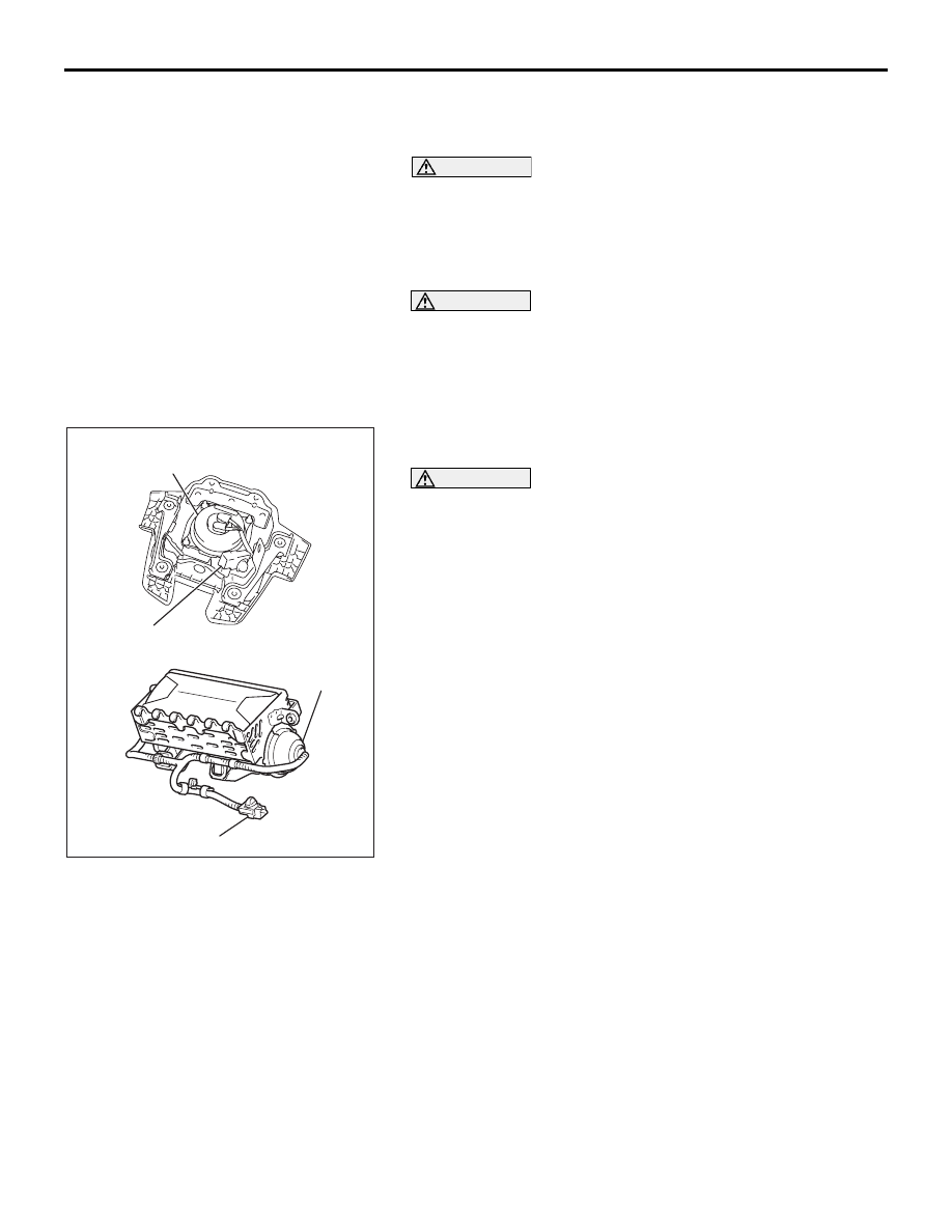
AC307662AB
<DRIVER'S SIDE>
<FRONT PASSENGER'S SIDE>
INFLATOR CASE
CONNECTOR
CONNECTOR
INFLATOR
CASE