Mitsubishi 380. Manual - part 828


  Index      Mitsubishi     Mitsubishi 380 - service repair manual 2005 year


Search            


Content   ..  826  827  828  829   ..


Mitsubishi 380. Manual - part 828


SRS CONTROL UNIT (SRS-ECU)

SUPPLEMENTAL RESTRAINT SYSTEM (SRS)

52B-236

INSTALLATION SERVICE POINTS

.

>>A<< SRS-ECU INSTALLATION

WARNING

The SRS may not activate if the SRS-ECU is not 
installed properly, which could result in serious injury 
or death to the vehicle's driver or front passenger.

Install the SRS-ECU with 10mm (3/8inch) slide head handle 
and 10mm (3/8inch) socket wrench.

.

>>B<< POST-INSTALLATION INSPECTION

1. Reconnect the negative (

−) battery cable.

2. Turn the ignition switch to the "ON" position.
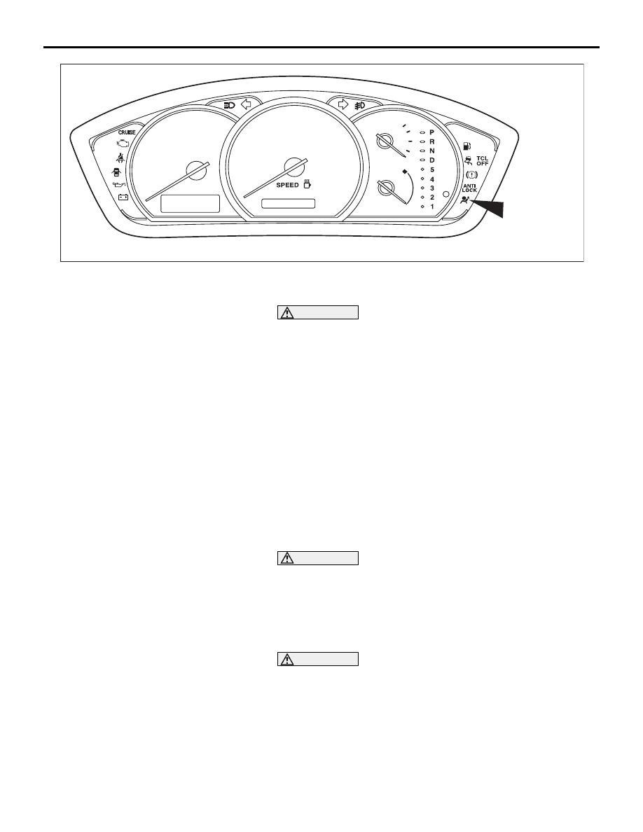
3. Does the "SRS" warning lamp illuminate for approximately 

seven seconds, and then go out?

4. If yes, the SRS system is functioning properly. If not, refer to 

P.52B-20

.

INSPECTION

M1524002200357

WARNING

If a dent, crack, deformation or rust is discovered, 
replace the SRS-ECU with a new one. 

• Check the SRS-ECU and brackets for dents, cracks or 

deformation. 

• Check the SRS-ECU connector for damage, and the termi-

nals for deformation. 

WARNING

[SRS is a safety related item, therefore there shall be no 
attempt to repair any component or wiring harness related 
to SRS]
 

NOTE: Refer to 

P.52B-215

 for inspection of SRS-ECU for other 

than physical damage. 

35DB113A

SRS 
WARNING 
LAMP

AIR BAG MODULES AND CLOCK SPRING

SUPPLEMENTAL RESTRAINT SYSTEM (SRS)

52B-237

AIR BAG MODULES AND CLOCK SPRING

M1524002400481

REMOVAL AND INSTALLATION

WARNING

Never attempt to disassemble or repair the air bag modules or clock spring. If faulty, 
replace it.

Do not drop the air bag modules or clock spring or allow contact with water, grease or oil. 
Replace it if a dent, crack, deformation or rust is detected.

The air bag modules should be stored on a flat surface with the pad cover facing upward. 
Do not place anything on top of it.

Do not expose the air bag modules to temperatures over 93

°C (200°F).

After deployment of an air bag, replace the clock spring with a new one.

Wear gloves and safety glasses when handling air bags that have already deployed.

An undeployed air bag module should only be disposed of in accordance with the proce-
dures (Refer to 

P.52B-254

).

AIR BAG MODULES AND CLOCK SPRING

SUPPLEMENTAL RESTRAINT SYSTEM (SRS)

52B-238

<Side-airbag module>

For removal and installation of the front seatback assembly with side-airbag module, refer to GROUP 52A, 
Front Seat 

P.52A-33

.

<Air bag module (driver's side) and clock spring>

AC307516AB

4

6

5

41 ± 8 N·m
30 ± 6 ft-lb

0.69 ± 0.15 N·m
6 ± 1 in-lb

A

B

B

COLUMN SWITCH

SECTION A - A

SECTION B - B

CLAW

CLAW

NOTE
          : CLAW POSITIONS

8

1

2

A

9.0 ± 2.0 N·m
80 ± 17 in-lb

8

N

7

3

3

3.9 ± 0.9 N·m
35 ± 8 in-lb

AIR BAG MODULE REMOVAL 
STEPS

<<A>>

1. NEGATIVE (

−) BATTERY CABLE 

CONNECTION

2. COVER

<<B>>

3. CONNECTORS (FOR HORN AND 

AIR BAG MODULE)

<<C>>

4. AIR BAG MODULE ASSEMBLY

CLOCK SPRING REMOVAL STEPS

<<A>>

1. NEGATIVE (

−) BATTERY CABLE 

CONNECTION

2. COVER

<<B>>

3. CONNECTORS (FOR HORN, AIR 

BAG MODULE AND STEERING 
WHEEL REMOTE CONTROL 
HARNESS)

<<C>>

4. AIR BAG MODULE ASSEMBLY
5. STEERING WHEEL DYNAMIC 

DAMPER

6. STEERING WHEEL REMOTE 

CONTROL HARNESS

<<D>>

7. STEERING WHEEL ASSEMBLY

COLUMN COVER LOWER (REFER 
TO GROUP 52A, INSTRUMENT 
PANEL 

P.52A-4

).

<<E>>

8. CLOCK SPRING

AIR BAG MODULE INSTALLATION 
STEPS

>>A<<

PRE-INSTALLATION INSPECTION

>>C<<

4. AIR BAG MODULE ASSEMBLY
3. CONNECTORS (FOR HORN AND 

AIR BAG MODULE)

2. COVER
1. NEGATIVE (

−) BATTERY CABLE 

CONNECTION

>>D<<

POST-INSTALLATION INSPECTION
CLOCK SPRING INSTALLATION 
STEPS

>>A<<

PRE-INSTALLATION INSPECTION

>>B<<

8. CLOCK SPRING

COLUMN COVER LOWER (REFER 
TO GROUP 52A, INSTRUMENT 
PANEL 

P.52A-4

).

>>C<<

7. STEERING WHEEL ASSEMBLY

CLOCK SPRING REMOVAL STEPS 

AIR BAG MODULES AND CLOCK SPRING

SUPPLEMENTAL RESTRAINT SYSTEM (SRS)

52B-239

Required Special Tools: 

•  MB991958 : diagnostic tool (MUT-III Sub Assem-

bly)

• MB991824: Vehicle Communication Interface 

(V.C.I.)

• MB991827: MUT-III USB Cable

• MB991910: MUT-III Main Harness A (Vehi-

cles with CAN communication system)

• MB991222: Probe

• MB990803: Steering  Wheel Puller 

<Air bag module (front passenger's side)>

6. STEERING WHEEL REMOTE 

CONTROL HARNESS

5. STEERING WHEEL DYNAMIC 

DAMPER

>>C<<

4. AIR BAG MODULE ASSEMBLY
3. CONNECTORS (FOR HORN, AIR 

BAG MODULE, AND STEERING 
WHEEL REMOTE CONTROL 
HARNESS)

2. COVER
1. NEGATIVE (

−) BATTERY CABLE 

CONNECTION

>>D<<

POST-INSTALLATION INSPECTION

CLOCK SPRING INSTALLATION 
STEPS (Continued)

52DB026A

1

4

3

2

AIR BAG MODULE REMOVAL 
STEPS

<<A>>

1. NEGATIVE (

−) BATTERY CABLE 

CONNECTION

<<B>>

2. CONNECTORS

INSTRUMENT PANEL ASSEMBLY 
(REFER TO GROUP 52A, 
INSTRUMENT PANEL 

P.52A-4

).

DISTRIBUTION DUCT (REFER TO 
GROUP 52A, INSTRUMENT PANEL 

P.52A-9

).

3. AIR BAG MODULE BRACKET

<<F>>

4. AIR BAG MODULE

AIR BAG MODULE INSTALLATION 
STEPS

>>A<<

PRE-INSTALLATION INSPECTION

4. AIR BAG MODULE
3. AIR BAG MODULE BRACKET

DISTRIBUTION DUCT (REFER TO 
GROUP 52A, INSTRUMENT PANEL 

P.52A-9

).

AIR BAG MODULE REMOVAL 
STEPS (Continued)


Content   ..  826  827  828  829   ..