Mitsubishi 380. Manual - part 803


  Index      Mitsubishi     Mitsubishi 380 - service repair manual 2005 year


Search            


Content   ..  801  802  803  804   ..


Mitsubishi 380. Manual - part 803


SRS AIR BAG DIAGNOSIS

SUPPLEMENTAL RESTRAINT SYSTEM (SRS)

52B-136

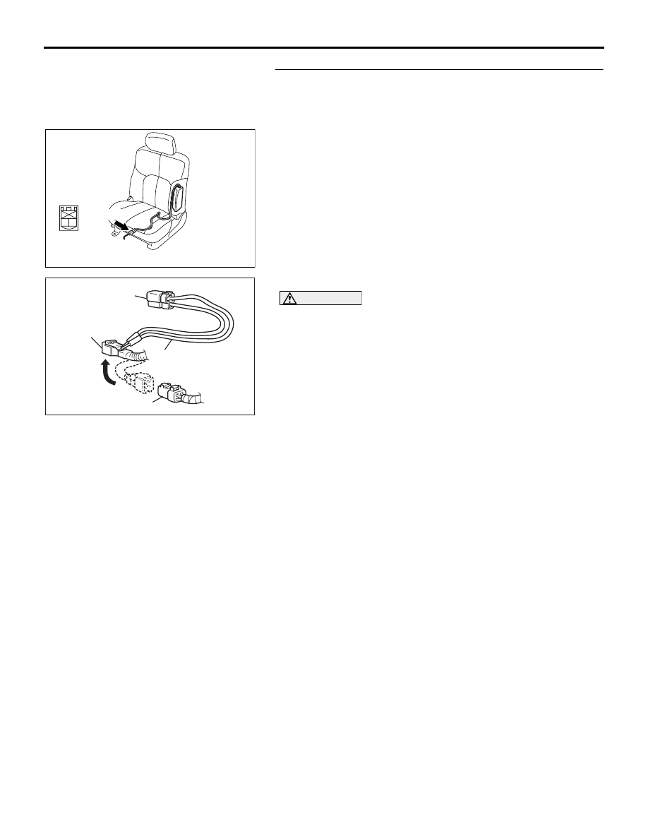
STEP 3. Check the side-airbag module (LH). (Using 
diagnostic tool MB991958, read the diagnostic trouble 
code.)
(1) Disconnect the negative battery terminal.
(2) Disconnect the side-airbag module (LH) connector D-24.

(3) Connect special tool MB991865 to special tool MB991866.

CAUTION

Do not insert a test probe into the terminal from its front 
side directly, as the connector contact pressure may be 
weakened.
(4) Insert special tool MB991866 into the D-24 harness side 

connector by testprobe.

(5) Connect the negative battery terminal.
(6) Erase the diagnostic trouble code memory, and check the 

diagnostic trouble code.

Q:  Is DTC B1432 set?

YES : Go to Step 4.
NO :  Replace the seatback frame of the front seat (LH) 

(Refer to GROUP 52A, Front Seat 

P.52A-33

). The

go to Step 6.

AC307778

CONNECTOR : D-24

AC

D-24 (R)

2

1

HARNESS SIDE
CONNECTOR
(REAR VIEW)

AC006042BP

MB991866
(RESISTOR HARNESS)

D-24 HARNESS SIDE
CONNECTOR

D-24 SIDE-AIRBAG 

MODULE (LH) CONNECTOR

MB991865 (DUMMY 
RESISTOR: 3


Ω)

SRS AIR BAG DIAGNOSIS

SUPPLEMENTAL RESTRAINT SYSTEM (SRS)

52B-137

STEP 4. Check the side-airbag module (RH) circuit. 
Measure the voltage at the SRS-ECU connector D-27.
(1) Disconnect SRS-ECU connector D-27.

DANGER

To prevent the air bag from deploying unintentionally, 
disconnect the side-airbag module (LH) connector 
D-24 to short the squib circuit.

(2) Disconnect left hand side-airbag module (LH) connector 

D-24.

(3) Turn the ignition switch to the "ON" position.

CAUTION

Do not insert a test probe into the terminal from its front 
side directly, as the connector contact pressure may be 
weakened.
(4) Measure the voltage between D-27 harness side connector 

terminals 9, 10 and body ground.
Voltage should measure 0 volt.

Q: Is the measured voltage within the specified range? 

YES : Erase the diagnostic trouble code memory, and check 

the diagnostic trouble code. If DTC B1432 sets, 
replace the SRS-ECU (Refer to 

P.52B-234

). Then go 

to Step 6.

NO :  Go to Step 5. 

24DB064A

CONNECTOR: D-27

SRS-ECU

D-27 (Y)

A

B

18

10

15

7

13

5

14

6

16

8

17

9

19

11

20

12

1 2

3 4

D-27 Floor 

harness

connector

(rear view)

AC307778

CONNECTOR : D-24

AC

D-24 (R)

2

1

HARNESS SIDE
CONNECTOR
(REAR VIEW)

24DB077A

A

B

18

10

15

7

13

5

14

6

16

8

17

9

19

11

20

12

1 2

3 4

D-27 FLOOR HARNESS 

SIDE CONNECTOR

(REAR VIEW)

SRS AIR BAG DIAGNOSIS

SUPPLEMENTAL RESTRAINT SYSTEM (SRS)

52B-138

STEP 5. Check the harness wires for short circuit to power 
supply between SRS-ECU connector D-27 (terminal No.9 
and 10) and side-airbag module (LH) connector D-24 
(terminal No.1 and 2). 
Q: Are the harness wires between SRS-ECU connector 

D-27 (terminal No.9 and 10) and side-airbag module (LH) 
connector D-24 (terminal No.1 and 2) in good condition?
YES : 
Go to Step 6.
NO :  Replace the harness wires between SRS-ECU 

connector D-27 and side-airbag module (LH) 
connector D-24. Then go to Step 6.

STEP 6. Recheck for diagnostic trouble code. 
Check again if the DTC is set.
(1) Erase the DTC.
(2) Turn the ignition switch to the "ON" position.
(3) Check if the DTC is set.
(4) Turn the ignition switch to the "LOCK" (OFF) position.

Q: Is DTC B1432 set?

YES : Return to Step 1.
NO :  The procedure is complete. 

AC307778

CONNECTOR : D-24

AC

D-24 (R)

2

1

HARNESS SIDE
CONNECTOR
(REAR VIEW)

24DB064A

CONNECTOR: D-27

SRS-ECU

D-27 (Y)

A

B

18

10

15

7

13

5

14

6

16

8

17

9

19

11

20

12

1 2

3 4

D-27 Floor 

harness

connector

(rear view)

00DB076A

MB991910

DATA LINK

CONNECTOR

MB991824

MB991827

SRS AIR BAG DIAGNOSIS

SUPPLEMENTAL RESTRAINT SYSTEM (SRS)

52B-139

DTC B1433: Side-Airbag Module (LH) (Squib) System Fault Ground Circuit (Short-Circuited to 
Ground)

CAUTION

If DTC B1433 is set in the combination meter, 
always diagnose the CAN bus lines.

.

CIRCUIT OPERATION

• The SRS-ECU judges how severe a collision is 

by detecting signals from the left and right side 
impact sensors. If the impact is over a predeter-
mined level, the SRS-ECU sends an ignition sig-
nal. At this time, if the side-airbag safing 
G-sensor is on, the SRS side-airbag will inflate.

• The ignition signal is input to the side-airbag 

module to inflate the side-airbag.

.

DTC SET CONDITIONS

This DTC is set if there is abnormal resistance 
between the input terminals of the side-airbag mod-
ule (LH) (squib).

.

TROUBLESHOOTING HINTS

• Damaged wiring harnesses or connectors

• Short to ground in the left hand side-airbag mod-

ule (squib) harness

• Malfunction of the SRS-ECU

• Refer to circuit diagrams GROUP-

90

• Refer to configuration diagrams GROUP-

80

.

DIAGNOSIS

Required Special Tools:

•  MB991958 : diagnostic tool (MUT-III Sub Assembly)

• MB991824: Vehicle Communication Interface (V.C.I.)

• MB991827: MUT-III USB Cable

• MB991910: MUT-III Main Harness A (Vehicles with CAN 

communication system)

• MB991865: Dummy resistor

• MB991866: Resistor harness

24DB064A

CONNECTOR: D-27

SRS-ECU

D-27 (Y)

A

B

18

10

15

7

13

5

14

6

16

8

17

9

19

11

20

12

1 2

3 4

D-27 Floor 

harness

connector

(rear view)

AC307778

CONNECTOR : D-24

AB

D-24 (R)


Content   ..  801  802  803  804   ..