Mitsubishi 380. Manual - part 740


  Index      Mitsubishi     Mitsubishi 380 - service repair manual 2005 year


Search            


Content   ..  738  739  740  741   ..


Mitsubishi 380. Manual - part 740


DIAGNOSIS

CONTROLLER AREA NETWORK (CAN)

54C-371

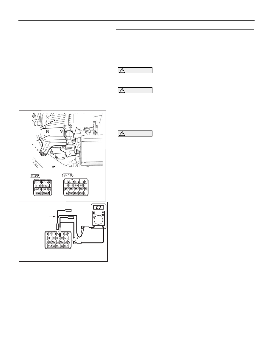
STEP 3. Check the CAN bus lines inside the A/T-ECU. 
Measure the resistance at A/T-ECU connector B-19.

NOTE: when diagnosing CAN-BUS on vehicles with 
manual transmission (M/T), disregard A/T-ECU and it’s wir-
ing circuits and check between ABS-ECU and 
ENGINE-ECU only.

CAUTION

A digital multimeter should be used. For details refer to 

P.54C-4

.

CAUTION

The test wiring harness should be used. For details refer to 

P.54C-4

.

(1) Disconnect A/T-ECU connector B-19, and measure the 

resistance at the component side of A/T-ECU connector 
B-19.

(2) Turn the ignition switch to the "LOCK" (OFF) position.

CAUTION

Disconnect the negative battery terminal. For details refer 
to 

P.54C-4

.

(3) Disconnect the negative battery terminal.

(4) Measure the resistance between A/T-ECU connector B-19 

terminals 14 and 5.

OK: 2 ohms or less

16DB480A

COVER

ENGINE

CONTROL

UNIT

AIR

CLEANER

A/T

CONTROL

UNIT

16DB518A

TEST
HARNESS

TEST
HARNESS

COMPONENT SIDE:  B-19

DIAGNOSIS

CONTROLLER AREA NETWORK (CAN)

54C-372

(5) Measure the resistance between A/T-ECU connector B-19 

terminals 4 and 13.

OK: 2 ohms or less

CAUTION

Strictly observe the specified wiring harness repair proce-
dure. For details refer to 

P.54C-5

.

Q: Do all the resistances measure 2 ohms or less?

YES : If all the resistances measure 2 ohms or less, power 

supply to the ENGINE-ECU may be suspected. 
Diagnose the engine. Refer to GROUP 13A, MPI 
diagnosis 

P.13A-571

.

NO :  If either or all of the resistances measures more than 

2  ohms, replace the A/T-ECU.

16DB519A

TEST
HARNESS

TEST
HARNESS

COMPONENT SIDE:  B-19

DIAGNOSIS

CONTROLLER AREA NETWORK (CAN)

54C-373

DIAGNOSTIC ITEM 12: Diagnose the lines between CAN main bus line and the A/T-ECU

NOTE: When diagnosing CAN-BUS on vehi-

cles with manual transmission (M/T), disregard 
A/T-ECU and it’s wiring circuits and measure 
between ABS-ECU and ENGINE-ECU only.

NOTE: When diagnosing CAN-BUS on vehicles 
not equipped with a multi-centre display, disre-
gard the multi-centre display and it’s wiring cir-
cuits.

CAUTION

When servicing a CAN bus line, ground yourself 
by touching a metal object such as an unpainted 
water pipe. If you fail to do so, a component con-
nected to the CAN bus line may be damaged.

.

TROUBLE JUDGMENT

If the MUT-III cannot received signals from the 
ENGINE-ECU, CAN bus line connector(s) are bro-
ken or an open circuit has occurred.

.

COMMENTS ON TROUBLE SYMPTOM

The wiring harness wire or connectors may have 
loose, corroded, or damage terminals, or terminals 
pushed back in the connector, or the ENGINE-ECU 
may be defective.

.

TROUBLESHOOTING HINTS

• Refer to circuit diagrams GROUP-

90

• Refer to configuration diagrams GROUP-

80

• The wiring harness or connectors may have 

loose, corroded, or damage terminals, or termi-
nals pushed back in the connector

• The ABS-ECU may be defective

• The A/T-ECU may be defective

NOTE: When diagnosing CAN-BUS on vehi-

cles with manual transmission (M/T), disregard 
A/T-ECU and it’s wiring circuits and measure 
between ABS-ECU and ENGINE-ECU only.

16DB402A

A-02 (GR)

CONNECTOR: A-02 

A-02 HARNESS CONNECTOR:

16DB400A

COVER

ENGINE

CONTROL

UNIT

AIR

CLEANER

16DB480A

COVER

ENGINE

CONTROL

UNIT

AIR

CLEANER

A/T

CONTROL

UNIT

DIAGNOSIS

CONTROLLER AREA NETWORK (CAN)

54C-374

DIAGNOSIS

Required Special Tools:

• MB991223: Harness Set

• MB991219: Inspection Test Harness

• MB992044: ENGINE-ECU Harness

• MB992045: A/T-ECU Harness

STEP 1. Check ABS-ECU connector A-02, A/T-ECU 
connector B-19 and ENGINE-ECU connector B-21 for 
loose, corroded or damaged terminals, or terminals 
pushed back in the connector.

CAUTION

The strand end of the twisted wire should be within 10 cm 
(4 inches) from the connector. For details refer to 

P.54C-4

.

Q: Are ABS-ECU connector A-02, A/T-ECU connector B-19 

and ENGINE-ECU connector B-21 in good condition? 
YES : 
Go to Step 2.
NO :  Repair the damaged parts.

16DB402A

A-02 (GR)

CONNECTOR: A-02 

A-02 HARNESS CONNECTOR:

16DB407A

COVER

ENGINE

CONTROL

UNIT

AIR

CLEANER

A/T

CONTROL

UNIT


Content   ..  738  739  740  741   ..