Mitsubishi 380. Manual - part 739
DIAGNOSIS
CONTROLLER AREA NETWORK (CAN)
54C-367
DIAGNOSTIC ITEM 9: Diagnose the lines between CAN main bus line and the ENGINE-ECU
NOTE: When diagnosing CAN-BUS on vehi-
cles with manual transmission (M/T), disregard
A/T-ECU and it’s wiring circuits and measure
between ABS-ECU and ENGINE-ECU only.
NOTE: When diagnosing CAN-BUS on vehicles
not equipped with a multi-centre display, disre-
gard the multi-centre display and it’s wiring cir-
cuits.
CAUTION
When servicing a CAN bus line, ground yourself
by touching a metal object such as an unpainted
water pipe. If you fail to do so, a component con-
nected to the CAN bus line may be damaged.
.
TROUBLE JUDGMENT
If the MUT-III cannot receive signals from the
ENGINE-ECU, CAN bus line connector(s) are bro-
ken or an open circuit has occurred.
.
COMMENTS ON TROUBLE SYMPTOM
The wiring harness wire or connectors may have
loose, corroded, or damage terminals, or terminals
pushed back in the connector, or the ENGINE-ECU
may be defective.
.
TROUBLESHOOTING HINTS
• Refer to circuit diagrams GROUP-
• Refer to configuration diagrams GROUP-
• The wiring harness or connectors may have
loose, corroded, or damage terminals, or termi-
nals pushed back in the connector
• The ENGINE-ECU may be defective
• The A/T-ECU may be defective
NOTE: When diagnosing CAN-BUS on vehi-
cles with manual transmission (M/T), disregard
A/T-ECU and it’s wiring circuits and measure
between ABS-ECU and ENGINE-ECU only.
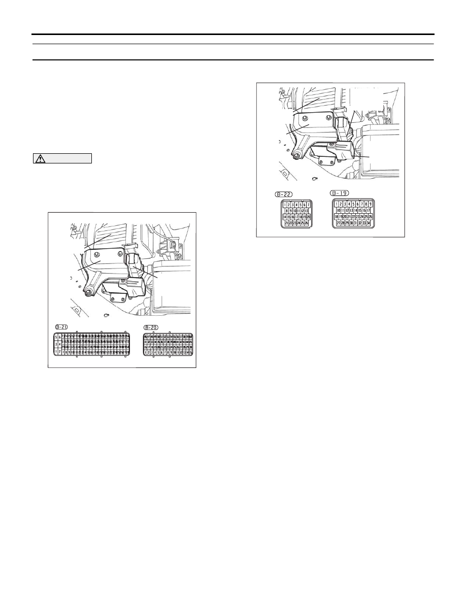
16DB400A
COVER
ENGINE
CONTROL
UNIT
AIR
CLEANER
16DB480A
COVER
ENGINE
CONTROL
UNIT
AIR
CLEANER
A/T
CONTROL
UNIT