Mitsubishi 380. Manual - part 738
DIAGNOSIS
CONTROLLER AREA NETWORK (CAN)
54C-363
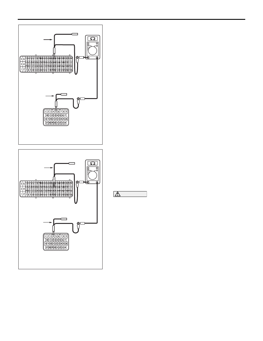
(4) Measure the resistance between A/T-ECU connector B-19
terminal 5 and ENGINE-ECU connector B-21 terminal 86.
OK: 2 ohms or less
(5) Measure the resistance between A/T-ECU connector B-19
terminal 4 and ENGINE-ECU connector B-21 terminal 64.
OK: 2 ohms or less
NOTE: when diagnosing CAN-BUS on vehicles with
manual transmission (M/T), disregard A/T-ECU and it’s wir-
ing circuits and check between ABS-ECU and
ENGINE-ECU only.
CAUTION
Strictly observe the specified wiring harness repair proce-
dure. For details refer to
Q: Do all the resistances measure 2 ohms or less?
YES : If all the resistances measure 2 ohms or less, go to
Step 29.
NO : If either of the resistances measures more than 2
ohms or all the resistances measure more than 2
ohms, repair the wiring harness between A/T-ECU
connector B-19 and the ENGINE-ECU connector
B-21.
16DB510A
HARNESS SIDE: B-19
TEST
HARNESS
TEST
HARNESS
HARNESS SIDE: B-21
16DB511A
HARNESS SIDE: B-19
TEST
HARNESS
TEST
HARNESS
HARNESS SIDE: B-21