Mitsubishi 380. Manual - part 736


  Index      Mitsubishi     Mitsubishi 380 - service repair manual 2005 year


Search            


Content   ..  734  735  736  737   ..


Mitsubishi 380. Manual - part 736


DIAGNOSIS

CONTROLLER AREA NETWORK (CAN)

54C-355

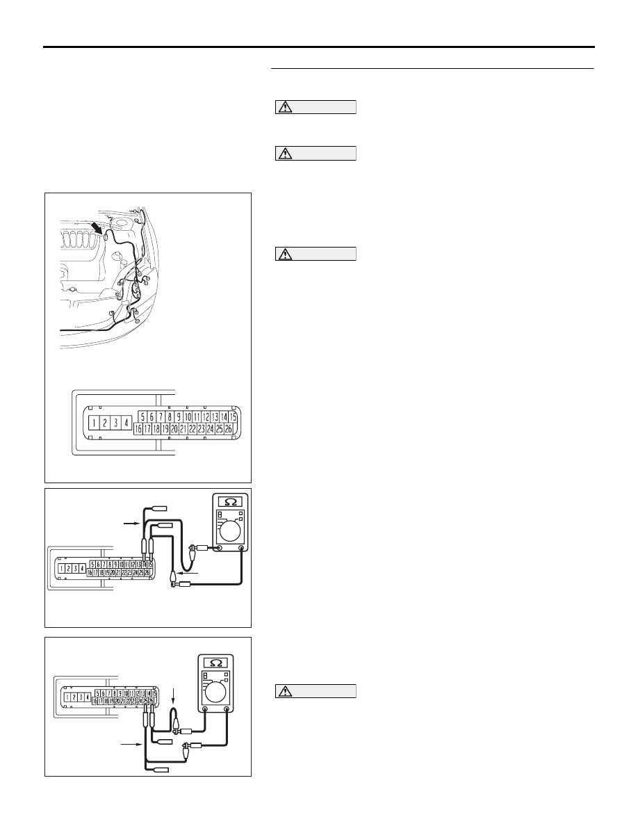
STEP 24. Check the CAN bus lines inside the ABS-ECU. 
Measure the resistance at ABS-ECU connector A-02.

CAUTION

A digital multimeter should be used. For details refer to 

P.54C-4

.

CAUTION

The test wiring harness should be used. For details refer to 

P.54C-4

.

(1) Disconnect ABS-ECU connector A-02, and measure the 

resistance at the component side of ABS-ECU connector 
A-02.

(2) Turn the ignition switch to the "LOCK" (OFF) position.

CAUTION

Disconnect the negative battery terminal. For details refer 
to 

P.54C-4

.

(3) Disconnect the negative battery terminal.

(4) Measure the resistance between ABS-ECU connector 

terminals 14 and 15.

OK: 2 ohms or less

(5) Measure the resistance between ABS-ECU connector 

terminals 25 and 26.

OK: 2 ohms or less

CAUTION

Strictly observe the specified wiring harness repair proce-
dure. For details refer to 

P.54C-5

.

Q: Do all the resistances measure 2 ohms or less?

YES  : If all the resistances measure 2 ohms or less, go to 

Step 25 or power supply to the ENGINE-ECU may be 
suspected. Diagnose the engine. Refer to GROUP 

16DB402A

A-02 (GR)

CONNECTOR: A-02 

A-02 HARNESS CONNECTOR:

16DB515A

COMPONENT SIDE: A-02

TEST 
HARNESS

TEST 
HARNESS

16DB516A

COMPONENT SIDE: A-02

TEST 
HARNESS

TEST 
HARNESS

DIAGNOSIS

CONTROLLER AREA NETWORK (CAN)

54C-356

13A, MPI diagnosis 

P.13A-571

 <3.8L engine>.

NO  :  If either of the resistances measures more than 2 

ohms or all the resistances measure more than 2 
ohms, replace the ABS-ECU.

STEP 25. Using diagnostic tool MB991958, diagnose the 
CAN bus line (Disconnect ABS-ECU connector A-02, and 
check the ABS-ECU system).
(1) Disconnect ABS-ECU connector A-02.
(2) Turn the ignition switch to the "ON" position.

16DB402A

A-02 (GR)

CONNECTOR: A-02 

A-02 HARNESS CONNECTOR:

DIAGNOSIS

CONTROLLER AREA NETWORK (CAN)

54C-357

(3) Diagnose CAN bus lines, and check if the MUT-III screen is 

as shown in the illustration.

NOTE: When diagnosing CAN-BUS on vehi-

cles with manual transmission (M/T), disregard 
A/T-ECU and it’s wiring circuits and measure 
between ABS-ECU and ENGINE-ECU only.

NOTE: When diagnosing CAN-BUS on vehicles 
not equipped with a multi-centre display, disre-
gard the multi-centre display and it’s wiring cir-
cuits.

(4) Turn the ignition switch to the "LOCK" (OFF) position.
(5) Check ABS-ECU connector A-02.

Q: Does the MUT-III screen correspond to the illustration?

YES  : If the MUT-III screen corresponds to the illustration, 

go to Step 26 .

NO  :  If the MUT-III screen does not correspond to the 

illustration, refer to diagnostics item 5: Check the 
CAN_L and H lines for a short circuit (Refer to 

P.54C-239

).

16DB593A

: Red section on screen

ENGINE

ECU

METER

-ECU

ETACS

-ECU

AC-ECU

SRS-ECU

C.DISPLAY

MUT

J/C

ABS-ECU

A/T-ECU

DIAGNOSIS

CONTROLLER AREA NETWORK (CAN)

54C-358

STEP 26. Check the CAN bus lines between intermediate 
connector C-29 and the ABS-ECU. Measure the resistance 
between intermediate connector C-29 and ABS-ECU 
connector A-02.

• Refer to circuit diagrams GROUP-

90

• Refer to configuration diagrams GROUP-

80

CAUTION

A digital multimeter should be used. For details refer to 

P.54C-4

.

CAUTION

The test wiring harness should be used. For details refer to 

P.54C-4

.

(1) Disconnect intermediate connector C-29 and ABS-ECU 

connector A-02, and measure the resistance between the 
wiring harness side connector of ABS-ECU connector A-02 
and the male side connector of intermediate connector 
C-29 (at front wiring harness side).

(2) Turn the ignition switch to the "LOCK" (OFF) position.

CAUTION

Disconnect the negative battery terminal. For details refer 
to 

P.54C-4

.

(3) Disconnect the negative battery terminal.

16DB402A

A-02 (GR)

CONNECTOR: A-02 

A-02 HARNESS CONNECTOR:

52DB014A

CONNECTOR: C-29


Content   ..  734  735  736  737   ..