Mitsubishi 380. Manual - part 734
DIAGNOSIS
CONTROLLER AREA NETWORK (CAN)
54C-347
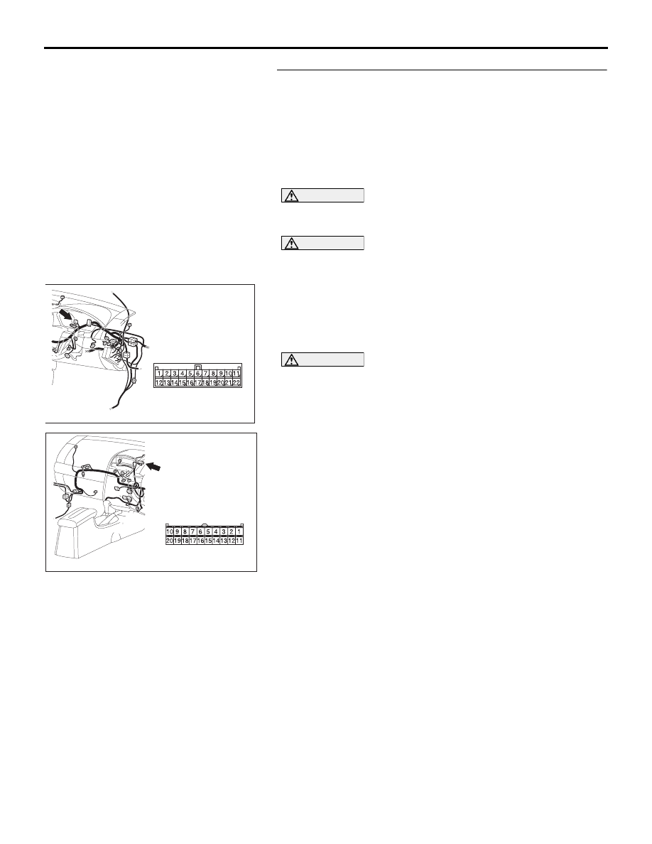
STEP 19. Check the CAN bus lines between joint
connector (3) and the multi-center display unit . Measure
the resistance between joint connector (3) C-02 and
multi-center display unit connector C-05.
NOTE: If diagnosing CAN-BUS on vehicle not equipped
with multi-centre display, go to Step 20.
• Refer to circuit diagrams GROUP-
• Refer to configuration diagrams GROUP-
CAUTION
A digital multimeter should be used. For details refer to
CAUTION
The test wiring harness should be used. For details refer to
(1) Disconnect joint connector (3) C-02 and multi-center display
unit connector C-05, and measure the resistance at the
wiring harness sides of joint connector (3) C-02 and
multi-center display unit connector C-05.
(2) Turn the ignition switch to the "LOCK" (OFF) position.
CAUTION
Disconnect the negative battery terminal. For details refer
to
.
(3) Disconnect the negative battery terminal.
16DB490A
CONNECTOR: C-05
HARNESS SIDE
C-05 (B)
16DB408A
CONNECTOR: C-02