Mitsubishi 380. Manual - part 733


  Index      Mitsubishi     Mitsubishi 380 - service repair manual 2005 year


Search            


Content   ..  731  732  733  734   ..


Mitsubishi 380. Manual - part 733


DIAGNOSIS

CONTROLLER AREA NETWORK (CAN)

54C-343

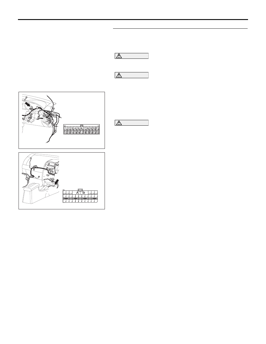
STEP 16. Check the CAN bus lines between joint 
connector (3) and the SRS-ECU connector. Measure the 
resistance between joint connector (3) C-02 and SRS-ECU 
connector C-121.

CAUTION

A digital multimeter should be used. For details refer to 

P.54C-4

.

CAUTION

The test wiring harness should be used. For details refer to 

P.54C-4

.

(1) Disconnect joint connector (3) C-02 and SRS-ECU 

connector C-121, and measure the resistance at the wiring 
harness sides of joint connector (3) C-02 and SRS-ECU 
connector C-121.

(2) Turn the ignition switch to the "LOCK" (OFF) position.

CAUTION

Disconnect the negative battery terminal. For details refer 
to 

P.54C-4

.

(3) Disconnect the negative battery terminal.

16DB478A

CONNECTOR: C-121

HARNESS SIDE

C-121 (Y)

48

21

22

23

24

25

26

27

28

29

30

31

32

33

34

35

36

37

38

39

40

41

42

43

44

45

46

47

16DB408A

CONNECTOR: C-02

DIAGNOSIS

CONTROLLER AREA NETWORK (CAN)

54C-344

(4) Measure the resistance between joint connector (3) 

terminal 3 and SRS-ECU connector C-121 terminal 32.

OK: 2 ohms or less

(5) Measure the resistance between joint connector (3) 

terminal 14 and SRS-ECU connector C-121 terminal 43.

OK: 2 ohms or less

CAUTION

Strictly observe the specified wiring harness repair proce-
dure. For details refer to 

P.54C-5

.

Q: Do all the resistances measure 2 ohms or less?

YES  : If all the resistances measure 2 ohms or less, power 

supply to the SRS-ECU may be suspected. Diagnose 
the supplemental restraint system. Refer to GROUP 
52B, SRS air bag diagnosis, equipment diagnosis 

P.52B-18

.

NO  :  If either of the resistances measures more than 2 

ohms or all the resistances measure more than 2 
ohms, repair the wiring harness between joint 
connector (3) and the SRS-ECU connector C-121. 

STEP 17. Check multi-center display unit  connector C-05 
for loose, corroded or damaged terminals, or terminals 
pushed back in the connector.

NOTE: If diagnosing CAN-BUS on vehicle not equipped 
with multi-centre display, go to Step 20.

16DB522A

HARNESS SIDE: C-02

TEST 
HARNESS

11
22

10
21

9

20

8

19

7

18

6

17

5

16

4

15

3

14

2

13

1

12

TEST 
HARNESS

HARNESS SIDE: C-121

48

21

22

23

24

25

26

27

28

29

30

31

32

33

34

35

36

37

38

39

40

41

42

43

44

45

46

47

16DB523A

11
22

10
21

9

20

8

19

7

18

6

17

5

16

4

15

3

14

2

13

1

12

TEST 
HARNESS

TEST 
HARNESS

HARNESS SIDE: C-02

HARNESS SIDE: C-121

48

21

22

23

24

25

26

27

28

29

30

31

32

33

34

35

36

37

38

39

40

41

42

43

44

45

46

47

DIAGNOSIS

CONTROLLER AREA NETWORK (CAN)

54C-345

CAUTION

The strand end of the twisted wire should be within 10 cm 
(4 inches) from the connector. For details refer to 

P.54C-4

.

Q: Is multi-center display unit  connector C-05 in good 

condition?
YES : 
Go to Step 18.
NO :  Repair the damaged parts.

STEP 18. Using diagnostic tool MB991958, diagnose the 
CAN bus line (Disconnect multi-center display unit  
connector C-05, and check the multi-center display unit  
system).

NOTE: If diagnosing CAN-BUS on vehicle not equipped 
with multi-centre display, go to Step 20.
(1) Disconnect multi-center display unit  connector C-05.
(2) Turn the ignition switch to the "ON" position.

16DB490A

CONNECTOR: C-05

HARNESS SIDE

C-05 (B)

16DB490A

CONNECTOR: C-05

HARNESS SIDE

C-05 (B)

DIAGNOSIS

CONTROLLER AREA NETWORK (CAN)

54C-346

(3) Diagnose CAN bus lines, and check if the MUT-III screen is 

as shown in the illustration.

NOTE: When diagnosing CAN-BUS on vehi-

cles with manual transmission (M/T), disregard 
A/T-ECU and it’s wiring circuits and measure 
between ABS-ECU and ENGINE-ECU only.

NOTE: When diagnosing CAN-BUS on vehicles 
not equipped with a multi-centre display, disre-
gard the multi-centre display and it’s wiring cir-
cuits.

(4) Turn the ignition switch to the "LOCK" (OFF) position.
(5) Connect the multi-center display unit  connector C-05.

Q: Does the MUT-III screen correspond to the illustration?

YES  : If the MUT-III screen corresponds to the illustration, 

go to Step 19 .

NO  :  If the MUT-III screen does not correspond to the 

illustration, go to Step 20.

16DB598A

: Red section on screen

ETACS

-ECU

AC-ECU

SRS-ECU

C.DISPLAY

MUT

J/C

METER

-ECU

ENGINE

ECU

ABS-ECU

A/T-ECU


Content   ..  731  732  733  734   ..