Mitsubishi 380. Manual - part 612


  Index      Mitsubishi     Mitsubishi 380 - service repair manual 2005 year


Search            


Content   ..  610  611  612  613   ..


Mitsubishi 380. Manual - part 612


MULTIPORT FUEL INJECTION (MPI) DIAG

MULTIPORT FUEL INJECTION (MPI)

13A-540

DIAGNOSIS

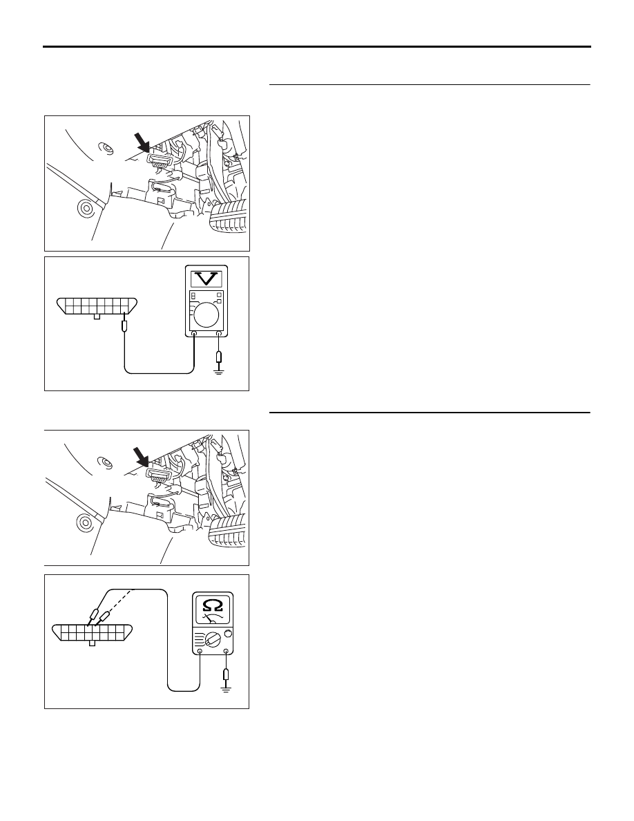
STEP 1. Measure the power supply voltage at data link 
connector C-125.
(1) Measure voltage between terminal No. 16 and ground.

• Voltage should be battery positive voltage.

Q: Is battery positive voltage (approximately 12 volts) 

present?
YES : 
Go to step 2.
NO :  Check harness connectors C-211, C-216 and C-29 at 

intermediate connector for damage, and repair or 
replace as required. Refer to GROUP 00E, Harness 
Connector Inspection 

P.00E-2

. If intermediate 

connector C-211, C-216 and C-29 are in good 
condition, repair an open circuit between fusible link 
(1) and data link connector C-125 (terminal No. 16). 
Then confirm that the malfunction symptom is 
eliminated.

STEP 2. Check the continuity at data link connector C-125.
(1) Check for the continuity between terminal No. 4, No. 5 and 

ground.

• Should be less than 2 ohms.

Q: Does continuity exist?

YES : Replace the diagnostic tool. Then confirm that the 

malfunction symptom is eliminated.

NO :  Repair an open circuit or harness damage between 

data link connector C-125 (terminal No. 4, No. 5) and 
ground. Then confirm that the malfunction symptom is 
eliminated.

03DB187A

CONNECTOR: C-125

DATA LINK 

CONNECTOR

AK303229

1 2 3 4 5 6 7 8

16

15

14

13

12

11

10

9

C-125 HARNESS 
CONNECTOR: 
COMPONENT SIDE

AB

03DB187A

CONNECTOR: C-125

DATA LINK 

CONNECTOR

AK303230

1 2 3 4 5 6 7 8

16

15

14

13

12

11

10

9

D-125 HARNESS 
CONNECTOR: 
COMPONENT SIDE

AB

MULTIPORT FUEL INJECTION (MPI) DIAG

MULTIPORT FUEL INJECTION (MPI)

13A-541

INSPECTION PROCEDURE 2: Diagnostic Tool Communication with ENGINE-ECU Is Not Possible.  

.

CIRCUIT OPERATION

• A diagnostic output is made from the 

ENGINE-ECU (terminal No. 44) to the diagnostic 
output terminal (terminal No. 7) of the data link 
connector.

.

COMMENT

• No power supply to ENGINE-ECU.

• Defective ground circuit of ENGINE-ECU.

• Defective ENGINE-ECU.

• Improper communication line between 

ENGINE-ECU and diagnostic tool.

.

TROUBLESHOOTING HINTS (The most 
likely causes for this case:) 

• Malfunction of ENGINE-ECU power supply cir-

cuit. 

• Malfunction of the ENGINE-ECU. 

• Open circuit between ENGINE-ECU and data link 

connector. 

• Refer to component locations GROUP-

70

• Refer to configuration diagrams GROUP-

80

• Refer to circuit diagrams GROUP-

90

03DB187A

CONNECTOR: C-125

DATA LINK 

CONNECTOR

16DB400A

COVER

ENGINE

CONTROL

UNIT

AIR

CLEANER

03DB171A

CONNECTOR: C-29

C-29

MULTIPORT FUEL INJECTION (MPI) DIAG

MULTIPORT FUEL INJECTION (MPI)

13A-542

DIAGNOSIS

STEP 1. Check harness connector B-21 at ENGINE-ECU for 
damage.
Q: Is the harness connector in good condition?

YES :  Go to Step 2.
NO :  Repair or replace it. Refer to GROUP 00E, Harness 

Connector Inspection 

P.00E-2

. Then confirm that the 

malfunction symptom is eliminated.

STEP2. Check for open circuit, short circuit to ground and 
harness damage between data link connector C-125 
(terminal No. 7) and ENGINE-ECU connector B-21 (terminal 
No. 44).

16DB400A

COVER

ENGINE

CONTROL

UNIT

AIR

CLEANER

03DB187A

CONNECTOR: C-125

DATA LINK 

CONNECTOR

16DB400A

COVER

ENGINE

CONTROL

UNIT

AIR

CLEANER

MULTIPORT FUEL INJECTION (MPI) DIAG

MULTIPORT FUEL INJECTION (MPI)

13A-543

NOTE: Check harness after checking intermediate connector 
C-29. If intermediate connector C-29 is damaged, repair or 
replace them. Refer to GROUP 00E, Harness Connector 
Inspection 

P.00E-2

. Then check that the malfunction is elimi-

nated.

Q: Is the harness wire in good condition?

YES : Refer to INSPECTION PROCEDURE 24 

− Power 

Supply System and Ignition Switch-IG System 

P.13A-604

.

NO :  Repair it. Then confirm that the malfunction symptom 

is eliminated.

INSPECTION PROCEDURE 3: The Malfunction Indicator Lamp (Check Engine Lamp) Does Not 
Illuminate Right after the Ignition Switch Is Turned to the "ON" Position.

.

COMMENT

• The combination meter causes the malfunction 

indicator lamp (Check Engine Lamp) to illuminate 
for 20 seconds immediately after the ignition 
switch is turned to the "ON" position occurred.

.

TROUBLESHOOTING HINTS (The most 
likely causes for this case:) 

• Malfunction of the malfunction indicator lamp 

(Check Engine Lamp).

• Open or shorted malfunction indicator lamp 

(Check Engine Lamp) circuit.

• Refer to component locations GROUP-

70

• Refer to configuration diagrams GROUP-

80

• Refer to circuit diagrams GROUP-

90

DIAGNOSIS

Required Special Tools:

• : Diagnostic tool (MUT-III Sub Assembly)

• MB991824: V.C.I.

• MB991827: USB Cable

• MB991910: Main Harness A


Content   ..  610  611  612  613   ..