Mitsubishi 380. Manual - part 613
MULTIPORT FUEL INJECTION (MPI) DIAG
MULTIPORT FUEL INJECTION (MPI)
13A-544
STEP 1. Using diagnostic tool , read the diagnostic trouble
code (DTC).
CAUTION
To prevent damage to diagnostic tool , always turn the
ignition switch to the "LOCK" (OFF) position before con-
necting or disconnecting diagnostic tool .
(1) Connect diagnostic tool to the data link connector.
(2) Turn the ignition switch to the "ON" position.
(3) Read the DTC.
(4) Turn the ignition switch to the "LOCK" (OFF) position.
Q: Is DTC set?
YES : Refer to Diagnostic Trouble Code Chart.
NO : Go to step 2.
STEP 2. Check the trouble symptoms.
(1) Turn the ignition switch to the "ON" position.
• The malfunction indicator lamp (Check Engine Lamp)
should illuminate immediately after the ignition switch is
turned to the "ON" position.
(2) Turn the ignition switch to the "LOCK" (OFF) position.
Q: Does the malfunction indicator lamp (Check Engine
Lamp) illuminate?
YES : It can be assumed that this malfunction is intermittent.
Refer to GROUP 00, How to Use
Troubleshooting/Inspection Service Points
− How to
Cope with Intermittent Malfunctions
.
NO : Replace the combination meter.
INSPECTION PROCEDURE 4: The Malfunction Indicator Lamp (Check Engine Lamp) Remains
Illuminated and Never Goes Out.
.
COMMENT
• In cases such as the above, the cause is proba-
bly that the ENGINE-ECU is detecting a problem
in a sensor or actuator, or that one of the mal-
functions listed at next has probably occurred.
.
TROUBLESHOOTING HINTS (The most
likely causes for this case:)
• Shorted the malfunction indicator lamp (Check
Engine Lamp) circuit.
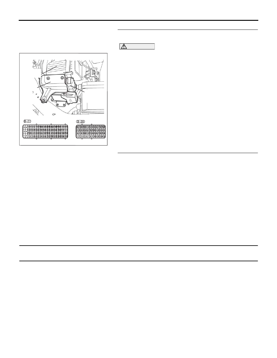
• Refer to component locations GROUP-
• Refer to configuration diagrams GROUP-
• Refer to circuit diagrams GROUP-
DIAGNOSIS
Required Special Tools:
• Diagnostic Tool (MUT-III Sub Assembly)
• MB991824: V.C.I.
16DB400A
COVER
ENGINE
CONTROL
UNIT
AIR
CLEANER