Mitsubishi 380. Manual - part 610
MULTIPORT FUEL INJECTION (MPI) DIAG
MULTIPORT FUEL INJECTION (MPI)
13A-532
DIAGNOSIS
Required Special Tools:
• : Diagnostic tool (MUT-III Sub Assembly)
• MB991824: V.C.I.
• MB991827: USB Cable
• MB991910: Main Harness A
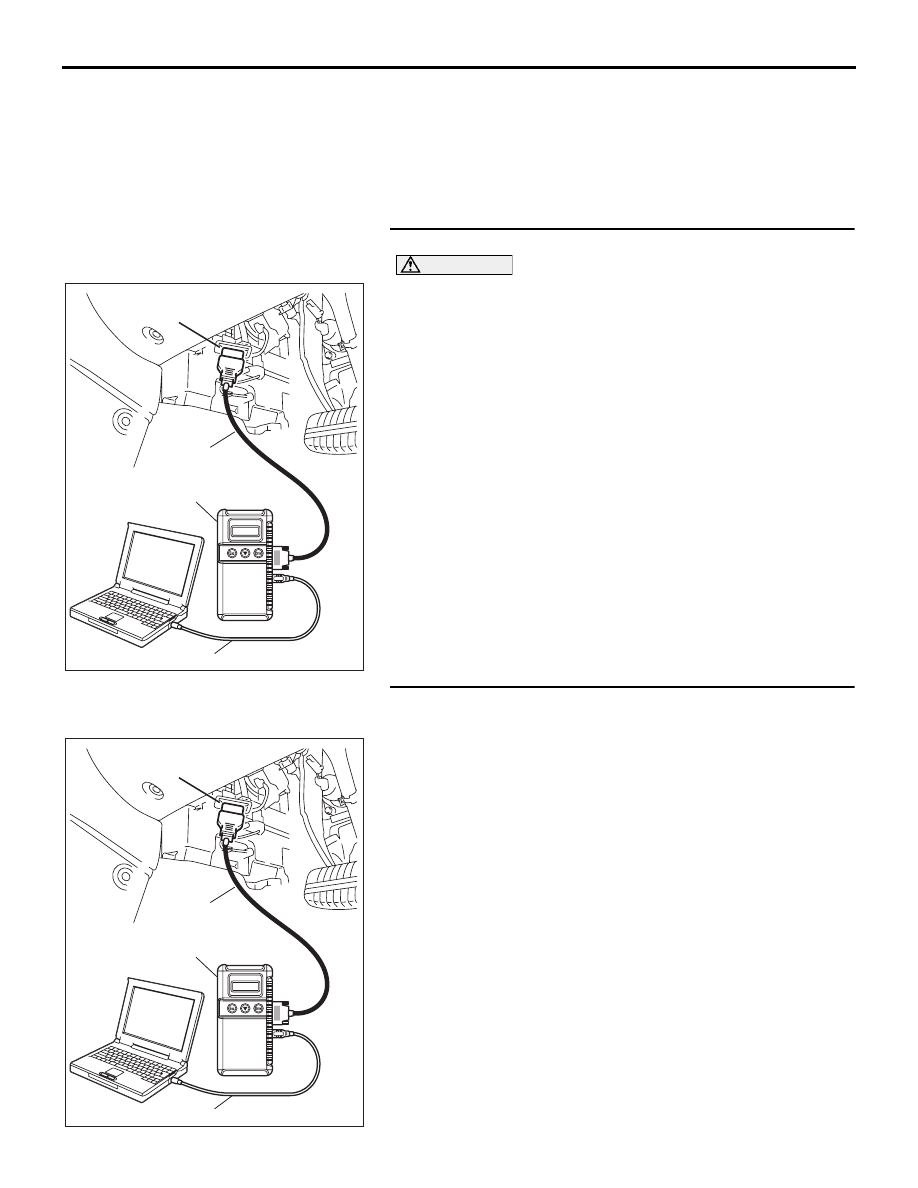
STEP 1. Using diagnostic tool , diagnose CAN bus line.
CAUTION
To prevent damage to diagnostic tool , always turn the
ignition switch to the "LOCK" (OFF) position before con-
necting or disconnecting diagnostic tool .
(1) Connect diagnostic tool to the data link connector.
(2) Turn the ignition switch to the "ON" position.
(3) Diagnose CAN bus line.
(4) Turn the ignition switch to the "LOCK" (OFF) position.
Q: Is the CAN bus line normal?
YES : Go to Step 2.
NO : Repair the CAN bus line. Refer to GROUP 54C, Can
Bus Diagnostics Table
. Then go to Step 6.
STEP 2. Using diagnostic tool , read the diagnostic trouble
code (DTC).
(1) Connect diagnostic tool to the data link connector.
(2) Turn the ignition switch to the "ON" position.
(3) Read the ABS-DTC.
(4) Turn the ignition switch to the "LOCK" (OFF) position.
Q: Is the ABS-DTC set?
YES : Refer to GROUP 35B, Anti-Lock Braking
System-Diagnostic Trouble Code Chart
NO : Go to Step 3.
00DB076A
MB991910
DATA LINK
CONNECTOR
MB991824
MB991827
00DB076A
MB991910
DATA LINK
CONNECTOR
MB991824
MB991827