Mitsubishi 380. Manual - part 600


  Index      Mitsubishi     Mitsubishi 380 - service repair manual 2005 year


Search            


Content   ..  598  599  600  601   ..


Mitsubishi 380. Manual - part 600


MULTIPORT FUEL INJECTION (MPI) DIAG

MULTIPORT FUEL INJECTION (MPI)

13A-492

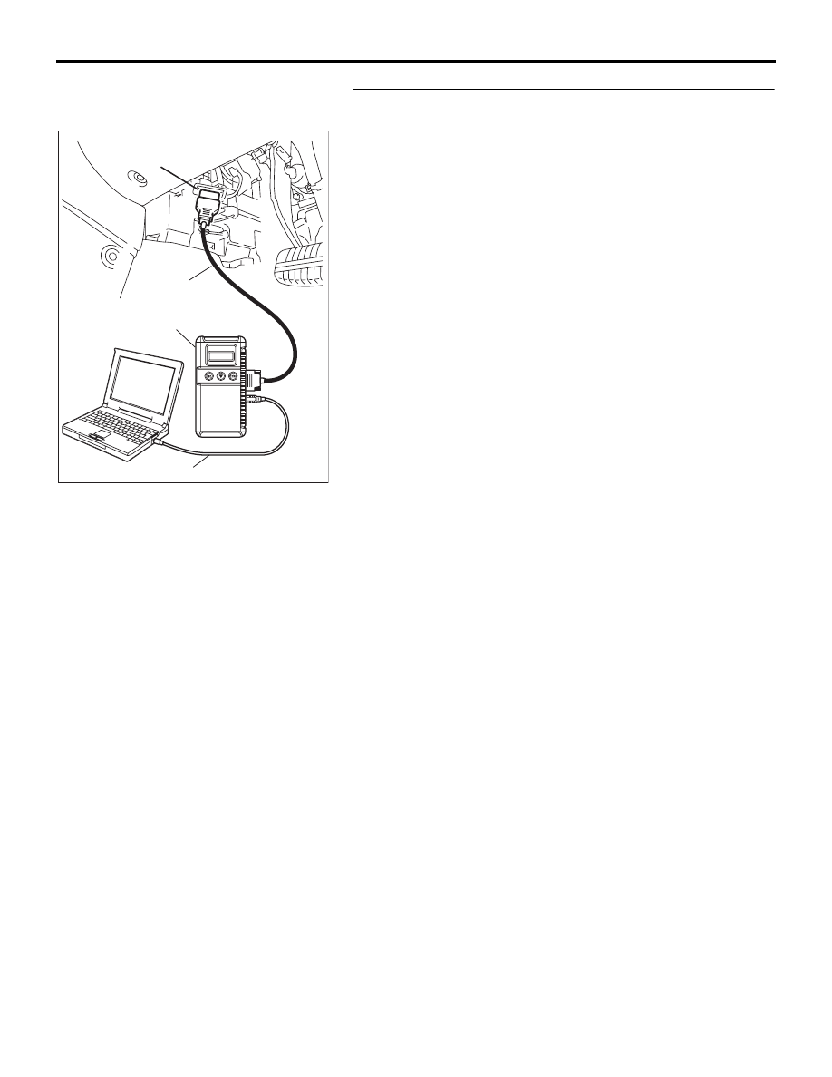
STEP 9. Using diagnostic tool , read the diagnostic trouble 
code (DTC).
(1) Connect diagnostic tool to the data link connector.
(2) Turn the ignition switch to the "ON" position.
(3) After the DTC has been deleted, read the DTC again.
(4) Turn the ignition switch to the "LOCK"(OFF) position.

Q: Is DTC P2123 set?

YES : Retry the troubleshooting.
NO :  The inspection is complete.

00DB076A

MB991910

DATA LINK

CONNECTOR

MB991824

MB991827

MULTIPORT FUEL INJECTION (MPI) DIAG

MULTIPORT FUEL INJECTION (MPI)

13A-493

DTC P2127: Accelerator Pedal Position Sensor (sub) Circuit Low Input.

.

CIRCUIT OPERATION

• A 5-volt power supply is applied on the accelera-

tor pedal position sensor (sub) power terminal 
(terminal No. 6) from the ENGINE-ECU (terminal 
No. 76).
The ground terminal (terminal No. 2) is grounded 
with ENGINE-ECU (terminal No. 35).

.

TECHNICAL DESCRIPTION

• The accelerator pedal position sensor (sub) out-

puts voltage which corresponds to the accelera-
tor pedal depression.

• The ENGINE-ECU checks whether the voltage is 

within a specified range.

.

DTC SET CONDITIONS

Check Conditions

• Ignition switch is "ON" position.

• Battery voltage is above 6.5 volt.

Judgement Criteria

• Accelerator pedal position sensor (sub) output 

voltage is below 0.43 volts for 0.2 second.

• MIL activated immediately.

• Engine speed limited to 1200rpm and power 

restricted.

.

EOBD DRIVE CYCLE PATTERN

None.

.

TROUBLESHOOTING HINTS (The most 
likely causes for this code to be set are:)

• Accelerator pedal position sensor failed.

• Open or shorted accelerator pedal position sen-

sor (sub) circuit. 

• Harness or connector damage.

• Refer to component locations GROUP-

70

• Refer to configuration diagrams GROUP-

80

• Refer to circuit diagrams GROUP-

90

DIAGNOSIS

Required Special Tools:

• : Diagnostic tool (MUT-III Sub Assembly)

• MB991824: V.C.I.

• MB991827: USB Cable

ACCELERATOR
PEDAL

CONNECTOR: C-24

C-24 (B)

ACCELERATOR 
PEDAL POSITION 
SENSOR

HARNESS
CONNECTOR:
COMPONENT SIDE

16DB562A

16DB400A

COVER

ENGINE

CONTROL

UNIT

AIR

CLEANER

MULTIPORT FUEL INJECTION (MPI) DIAG

MULTIPORT FUEL INJECTION (MPI)

13A-494

• MB991910: Main Harness A

STEP 1. Using diagnostic tool , check data list item 12: 
Accelerator Pedal Position Sensor (sub).

CAUTION

To prevent damage to diagnostic tool , always turn the 
ignition switch to the "LOCK"(OFF) position before con-
necting or disconnecting diagnostic tool .
(1) Connect diagnostic tool to the data link connector.
(2) Turn the ignition switch to the "ON" position.
(3) Set diagnostic tool to the data reading mode for


item 12, 

Accelerator Pedal Position Sensor (sub).

• Output voltage is between 0435 and 1035 mV when foot 

is released from accelerator pedal.

• Output voltage is between 4000 - 4824 mV when accel-

erator pedal is fully depressed.

(4) Turn the ignition switch to the "LOCK"(OFF) position.

Q: Is the sensor operating properly?

YES : It can be assumed that this malfunction is intermittent. 

Refer to GROUP 00, How to Use 
Troubleshooting/Inspection Service Points 

− How to 

Cope with Intermittent Malfunctions 

P.00-14

.

NO :  Go to Step 2.

STEP 2. Check harness connector C-24 at accelerator 
pedal position sensor for damage.
Q: Is the harness connector in good condition?

YES : Go to Step 3.
NO :  Repair or replace it. Refer to GROUP 00E, Harness 

Connector Inspection 

P.00E-2

. Then go to Step 10.

00DB076A

MB991910

DATA LINK

CONNECTOR

MB991824

MB991827

ACCELERATOR
PEDAL

CONNECTOR: C-24

C-24 (B)

ACCELERATOR 
PEDAL POSITION 
SENSOR

HARNESS
CONNECTOR:
COMPONENT SIDE

16DB562A

MULTIPORT FUEL INJECTION (MPI) DIAG

MULTIPORT FUEL INJECTION (MPI)

13A-495

STEP 3. Measure the sensor supply voltage at accelerator 
pedal position sensor harness side connector C-24.
(1) Disconnect the connector C-24 and measure at the harness 

side.

(2) Turn the ignition switch to the "ON" position.

(3) Measure the voltage between terminal No. 6 and ground.

• Voltage should be between 4.9 and 5.1 volts.

(4) Turn the ignition switch to the "LOCK"(OFF) position.

Q: Is the measured voltage between 4.9 and 5.1 volts?

YES : Go to Step 7.
NO :   Go to Step 4.

ACCELERATOR
PEDAL

CONNECTOR: C-24

C-24 (B)

ACCELERATOR 
PEDAL POSITION 
SENSOR

HARNESS
CONNECTOR:
COMPONENT SIDE

16DB562A

1

6 5 4 3 2

03DB253A

C-24 HARNESS 

CONNECTOR: 

COMPONENT SIDE


Content   ..  598  599  600  601   ..