Mitsubishi 380. Manual - part 599


  Index      Mitsubishi     Mitsubishi 380 - service repair manual 2005 year


Search            


Content   ..  597  598  599  600   ..


Mitsubishi 380. Manual - part 599


MULTIPORT FUEL INJECTION (MPI) DIAG

MULTIPORT FUEL INJECTION (MPI)

13A-488

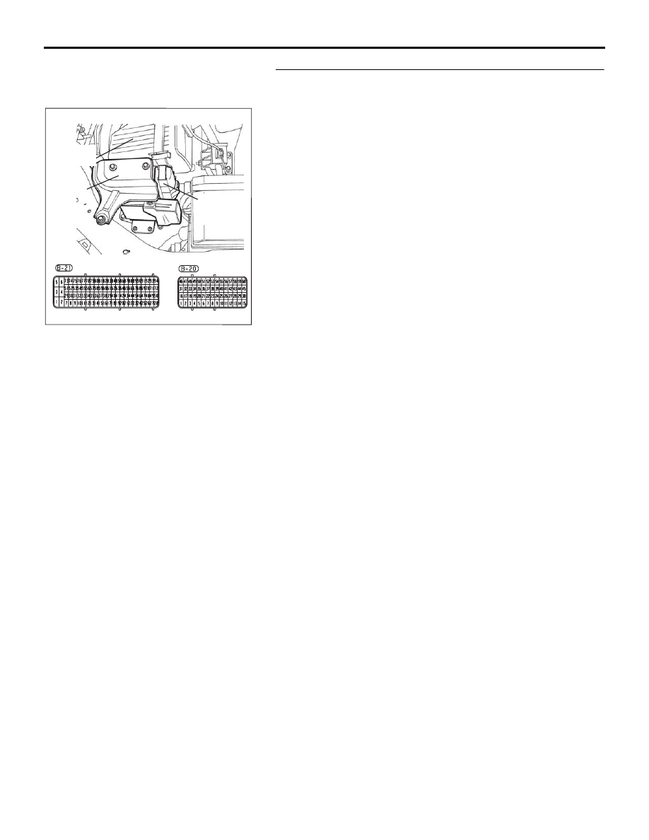
STEP 4. Check harness connector B-21 at ENGINE-ECU for 
damage.
Q: Is the harness connector in good condition?

YES : Go to Step 5.
NO :  Repair or replace it. Refer to GROUP 00E, Harness 

Connector Inspection 

P.00E-2

. Then go to Step 9.

16DB400A

COVER

ENGINE

CONTROL

UNIT

AIR

CLEANER

MULTIPORT FUEL INJECTION (MPI) DIAG

MULTIPORT FUEL INJECTION (MPI)

13A-489

STEP 5. Check for open circuit and harness damage 
between accelerator pedal position sensor connector C-24 
(terminal No. 4) and ENGINE-ECU connector B-21 (terminal 
No. 13).
Q: Is the harness wire in good condition?

YES : Go to Step 6.
NO :  Repair or replace it. Then go to Step 9.

ACCELERATOR
PEDAL

CONNECTOR: C-24

C-24 (B)

ACCELERATOR 
PEDAL POSITION 
SENSOR

HARNESS
CONNECTOR:
COMPONENT SIDE

16DB562A

16DB400A

COVER

ENGINE

CONTROL

UNIT

AIR

CLEANER

MULTIPORT FUEL INJECTION (MPI) DIAG

MULTIPORT FUEL INJECTION (MPI)

13A-490

STEP 6. Check for short circuit to 5-Volts and harness 
damage between throttle position sensor connector C-24 
(terminal No. 4) and ECU connector B-21 (terminal No. 13).
Q: Is the harness wire in good condition?

YES : Go to Step 7.
NO :  Repair or replace it. Then go to Step 9.

ACCELERATOR
PEDAL

CONNECTOR: C-24

C-24 (B)

ACCELERATOR 
PEDAL POSITION 
SENSOR

HARNESS
CONNECTOR:
COMPONENT SIDE

16DB562A

16DB400A

COVER

ENGINE

CONTROL

UNIT

AIR

CLEANER

MULTIPORT FUEL INJECTION (MPI) DIAG

MULTIPORT FUEL INJECTION (MPI)

13A-491

STEP 7. Replace the accelerator pedal position sensor.
(1) Replace the accelerator pedal position sensor.
(2) Turn the ignition switch to the "ON" position.
(3) After the DTC has been deleted, read the DTC again.
(4) Turn the ignition switch to the "LOCK" (OFF) position.

Q: Is DTC P2123 set?

YES : Then go to Step 8.
NO :  The inspection is complete.

STEP 8. Using diagnostic tool , check data list item 11: 
Accelerator Pedal Position Sensor (main).

CAUTION

To prevent damage to diagnostic tool , always turn the 
ignition switch to the "LOCK"(OFF) position before con-
necting or disconnecting diagnostic tool .
(1) Connect diagnostic tool to the data link connector.
(2) Turn the ignition switch to the "ON" position.
(3) Set diagnostic tool to the data reading mode for


item 11, 

Accelerator Pedal Position Sensor (main).

• Output voltage is between 435 and 1035 mV when foot 

is released from accelerator pedal.

• Output voltage is between 4000 - 4824 mV when accel-

erator pedal is fully depressed.

(4) Turn the ignition switch to the "LOCK"(OFF) position.

Q: Is the sensor operating properly?

YES : It can be assumed that this malfunction is intermittent. 

Refer to GROUP 00, How to Use 
Troubleshooting/Inspection Service Points 

− How to 

Cope with Intermittent Malfunctions 

P.00-14

.

NO :  Then go to Step 9.

ACCELERATOR
PEDAL

CONNECTOR: C-24

C-24 (B)

ACCELERATOR 
PEDAL POSITION 
SENSOR

HARNESS
CONNECTOR:
COMPONENT SIDE

16DB562A

00DB076A

MB991910

DATA LINK

CONNECTOR

MB991824

MB991827


Content   ..  597  598  599  600   ..