Mitsubishi 380. Manual - part 587


  Index      Mitsubishi     Mitsubishi 380 - service repair manual 2005 year


Search            


Content   ..  585  586  587  588   ..


Mitsubishi 380. Manual - part 587


MULTIPORT FUEL INJECTION (MPI) DIAG

MULTIPORT FUEL INJECTION (MPI)

13A-440

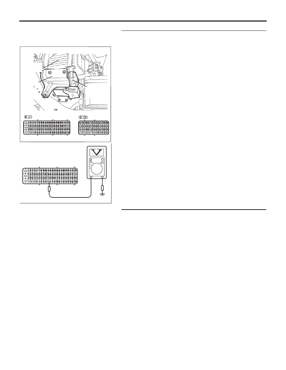
STEP 3. Measure the backup power supply voltage at 
ENGINE-ECU harness side connector B-21.
(1) Disconnect the ENGINE-ECU connector B-21 and measure 

at the harness side.

(2) Measure the voltage between terminal No. 16 and ground.

• Voltage should be battery positive voltage.

Q: Is battery positive voltage (approximately 12 volts) 

present?
YES : 
Go to Step 5.
NO :  Then go to Step 4.

STEP 4. Check No. 9 fuse, 20 A in Relay box.

Q: Is the Fuse servicable and in good condition?

YES : Repair harness wire between battery and 

ENGINE-ECU connector B-21 (terminal No. 16) 
because of harness damage. Then go to Step 6.

NO :  Replace the fuse. Then go to Step 7.

16DB400A

COVER

ENGINE

CONTROL

UNIT

AIR

CLEANER

03DB183A

B-21HARNESS 

CONNECTOR 

MULTIPORT FUEL INJECTION (MPI) DIAG

MULTIPORT FUEL INJECTION (MPI)

13A-441

STEP 5. Check harness connector B-21 at ENGINE-ECU for 
damage.
Q: Is the harness connector in good condition?

YES : Then go to Step 6.
NO :  Repair or replace it. Refer to GROUP 00E, Harness 

Connector Inspection 

P.00E-2

. Then go to Step 7.

STEP 6. Check harness connector B-21 at ENGINE-ECU for 
damage.
Q: Is the harness connector in good condition?

YES : Replace the ENGINE-ECU. Then go to Step 7.
NO :  Repair or replace it. Refer to GROUP 00E, Harness 

Connector Inspection 

P.00E-2

. Then go to Step 7.

16DB400A

COVER

ENGINE

CONTROL

UNIT

AIR

CLEANER

16DB400A

COVER

ENGINE

CONTROL

UNIT

AIR

CLEANER

MULTIPORT FUEL INJECTION (MPI) DIAG

MULTIPORT FUEL INJECTION (MPI)

13A-442

STEP 7. Using diagnostic tool , read the diagnostic trouble 
code (DTC).

CAUTION

To prevent damage to diagnostic tool , always turn the 
ignition switch to the "LOCK" (OFF) position before con-
necting or disconnecting diagnostic tool .
(1) Connect diagnostic tool to the data link connector.
(2) Turn the ignition switch to the "ON" position.
(3) Read the DTC.
(4) Turn the ignition switch to the "LOCK" (OFF) position.

Q: Is DTC P1603 set?

YES : Retry the troubleshooting.
NO :  The inspection is complete.

00DB076A

MB991910

DATA LINK

CONNECTOR

MB991824

MB991827

MULTIPORT FUEL INJECTION (MPI) DIAG

MULTIPORT FUEL INJECTION (MPI)

13A-443

DTC P2096: Post Catalyst System too Lean (bank 1)

.

TECHNICAL DESCRIPTION

• The signal from the rear heated oxygen sensor 

differs from the front heated oxygen sensor. That 
is because the catalytic converter purifies 
exhaust gas. When the catalytic converter or oxy-
gen sensor has deteriorated, the signal from the 
front heated oxygen sensor becomes similar to 
the rear heated oxygen sensor.

• The ECU compares the output of the front and 

rear heated oxygen sensor signals.

.

DTC SET CONDITIONS

Check Conditions

• None

Judgment Criteria

• Oxygen sensor slow response.

• MIL activated after 2 drive cycles.

• No Limp home.

.

EOBD DRIVE CYCLE PATTERN

Refer to Diagnostic Function 

− EOBD Drive Cycle − 

P.13A-11

.

.

TROUBLESHOOTING HINTS (The most 
likely causes for this code to be set are: )

• Right bank heated oxygen sensor deterio-

rated/failed.

• Right bank side catalytic converter deteriorated.

• Exhaust leak.

• Refer to component locations GROUP-

70

• Refer to configuration diagrams GROUP-

80

• Refer to circuit diagrams GROUP-

90

DIAGNOSIS

Required Special Tools:

• Diagnostic tool (MUT-III Sub Assembly)

• MB991824: V.C.I.

• MB991827: USB Cable

• MB991910: Main Harness A

STEP 1. Check for exhaust leak.

Q: Are there any abnormalities?

YES : Repair it. Then go to Step 7.
NO :  Go to Step 2.


Content   ..  585  586  587  588   ..