Mitsubishi 380. Manual - part 585


  Index      Mitsubishi     Mitsubishi 380 - service repair manual 2005 year


Search            


Content   ..  583  584  585  586   ..


Mitsubishi 380. Manual - part 585


MULTIPORT FUEL INJECTION (MPI) DIAG

MULTIPORT FUEL INJECTION (MPI)

13A-432

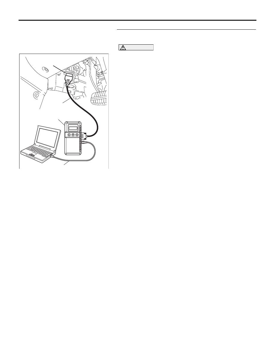
STEP 1. Using diagnostic tool , check data list item 59: 
Target ETV Value.

CAUTION

To prevent damage to diagnostic tool , always turn the 
ignition switch to the "LOCK"(OFF) position before con-
necting or disconnecting diagnostic tool .
(1) Connect diagnostic tool to the data link connector.
(2) Turn the ignition switch to the "ON" position.
(3) Set diagnostic tool to the data reading mode for item 59, 

Target ETV Value.

• Check that it is between 0.6 and 1.2 volts.

(4) Turn the ignition switch to the "LOCK"(OFF) position.

Q: Is the measured voltage between 0.6 and 1.2 volts?

YES : Go to Step 2..
NO :  Replace the throttle body assembly. Then go to Step 

8.

00DB076A

MB991910

DATA LINK

CONNECTOR

MB991824

MB991827

MULTIPORT FUEL INJECTION (MPI) DIAG

MULTIPORT FUEL INJECTION (MPI)

13A-433

WARNING

If the air intake duct is removed from the throttle body take great care to keep fingers away 
from the throttle plate. The drive motor has very high torque and is capable of random move-
ment at any time. Do not under any circumstances activate the throttly plate by hand.
When removing the throttle body from the intake manifold disconnect the wiring first. During 
replacement connect the wiring last.
Do not activate the throttle body using a DC suppy to test the motor,as permanent damage to 
the throttle body will result.

STEP 2. Check the throttle actuator control motor.
(1) Disconnect the connector B-06.

(2) Measure the resistance between throttle actuator control 

motor side connector terminal No. 1 and No. 4.

Standard value: 1.5 

± 0.3 ohms [at 20°C]

Q: Is the measured resistance between the standard 

value?
YES : 
Go to Step 3.
NO :  Replace the throttle body assembly. Then go to Step 

8.

STEP 3. Check harness connector B-06 at throttle actuator 
control motor for damage.
Q: Is the harness connector in good condition?

YES : Go to Step 4.
NO :  Repair or replace it. Refer to GROUP 00E, Harness 

Connector Inspection 

P.00E-2

. Then go to Step 8..

03DB180A

CONNECTOR: B-06

B-06 (B)

03DB181A

THROTTLE ACTUATOR

CONTROL MOTOR 

CONNECTOR

03DB180A

CONNECTOR: B-06

B-06 (B)

MULTIPORT FUEL INJECTION (MPI) DIAG

MULTIPORT FUEL INJECTION (MPI)

13A-434

STEP 4. Check harness connector B-20 at ENGINE-ECU for 
damage.
Q: Is the harness connector in good condition?

YES : Go to Step 5.
NO :  Repair or replace it. Refer to GROUP 00E, Harness 

Connector Inspection 

P.00E-2

. Then go to Step 8.

STEP 5. Check for harness damage between throttle 
actuator control motor connector B-06 (terminal No. 4) and 
ENGINE-ECU connector B-20 (terminal No. 50).
Q: Is the harness wire in good condition?

YES : Go to Step 6.
NO :  Repair it. Then go to Step 8.

16DB400A

COVER

ENGINE

CONTROL

UNIT

AIR

CLEANER

03DB180A

CONNECTOR: B-06

B-06 (B)

16DB400A

COVER

ENGINE

CONTROL

UNIT

AIR

CLEANER

MULTIPORT FUEL INJECTION (MPI) DIAG

MULTIPORT FUEL INJECTION (MPI)

13A-435

STEP 6. Check for harness damage between throttle 
actuator control motor connector B-06 (terminal No. 1) and 
ENGINE-ECU connector B-20 (terminal No. 49).
Q: Is the harness wire in good condition?

YES : Go to Step 7.
NO :  Repair it. Then go to Step 8.

03DB180A

CONNECTOR: B-06

B-06 (B)

16DB400A

COVER

ENGINE

CONTROL

UNIT

AIR

CLEANER


Content   ..  583  584  585  586   ..