Mitsubishi 380. Manual - part 558
MULTIPORT FUEL INJECTION (MFI) DIAGNOSIS
MULTIPORT FUEL INJECTION (MFI)
13A-324
DTC P0223: Throttle Position Sensor (Sub) Circuit High Input.
.
CIRCUIT OPERATION
• A 5-volt power supply is applied on the throttle
position sensor (sub) power terminal (terminal
No. 3) from the ENGINE-ECU(terminal No. 10).
The throttle position sensor (sub) outputs a volt-
age from (terminal No. 5) to the
ENGINE-ECU(terminal No. 57).
The ground terminal (terminal No. 2) is grounded
with ECU (terminal No. 27).
.
TECHNICAL DESCRIPTION
• The throttle position sensor (sub) outputs voltage
which corresponds to the throttle valve opening
angle.
• The ECU checks whether the voltage is within a
specified range.
.
DTC SET CONDITIONS
Check Conditions
• Ignition switch is "ON" position.
• TPS is normal.
Judgement Criteria
• MIL is actvated immediately.
• Vehicle in Limp home - Engine speed limited to
1500rpm.
.
EOBD DRIVE CYCLE PATTERN
None.
.
TROUBLESHOOTING HINTS (The most
likely causes for this code to be set are:)
• Throttle position sensor failed.
• Short circuit to 5 Volts in throttle position sensor
(sub) circuit.
• Harness or connector damage
• Refer to component locations GROUP-
• Refer to configuration diagrams GROUP-
• Refer to circuit diagrams GROUP-
DIAGNOSIS
Required Special Tools:
• Diagnostic Tool (MUT-III Sub Assembly)
• MB991824: V.C.I.
• MB991827: USB Cable
• MB991910: Main Harness A
• MB992044: Power Plant ECU Check Harness
03DB180A
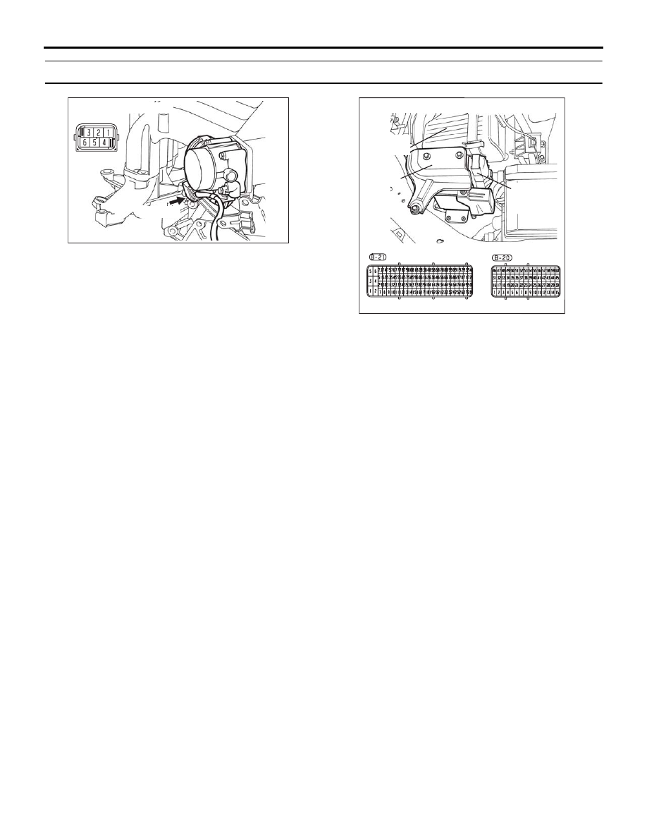
CONNECTOR: B-06
B-06 (B)
16DB400A
COVER
ENGINE
CONTROL
UNIT
AIR
CLEANER