Mitsubishi 380. Manual - part 556


  Index      Mitsubishi     Mitsubishi 380 - service repair manual 2005 year


Search            


Content   ..  554  555  556  557   ..


Mitsubishi 380. Manual - part 556


MULTIPORT FUEL INJECTION (MFI) DIAGNOSIS

MULTIPORT FUEL INJECTION (MFI)

13A-316

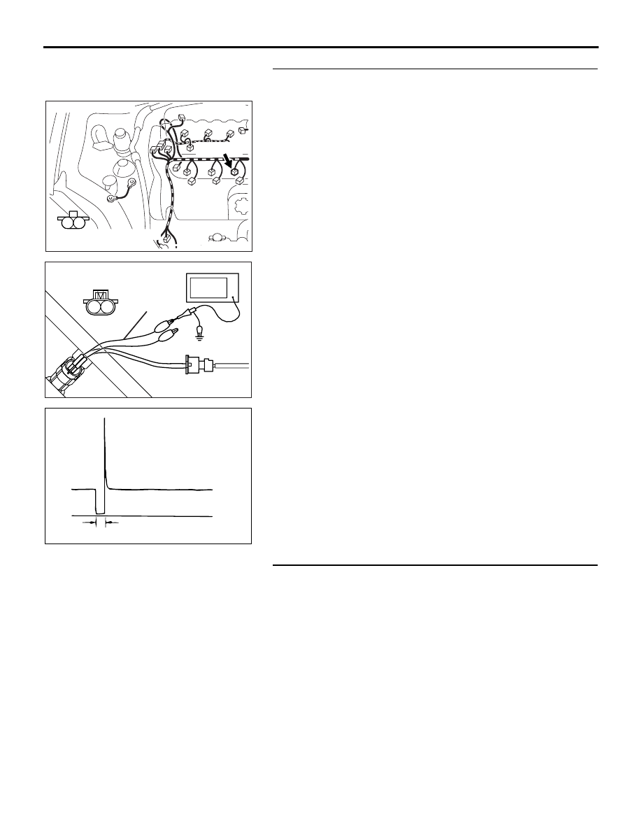
STEP 9. Using the oscilloscope, check the No. 6 cylinder 
injector.
(1) Disconnect the No. 6 cylinder injector connector B-26 and 

connect the test harness special tool (MB991658) between 
the separated connectors. (All terminals should be 
connected)

(2) Connect the oscilloscope probe to the injector side 

connector terminal No. 2.

NOTE: When measuring with the ECU side connector, dis-
connect the all ECU connectors and connect check harness 
special tool (MB992044) between the separated connec-
tors. Then connect an oscilloscope probe to the check har-
ness connector terminal No. 17.

(3) Start the engine and run at idle.

(4) Measure the waveform.

• The waveform should show a normal pattern similar to 

the illustration.

(5) Turn the ignition switch to the "LOCK" (OFF) position.

Q: Is the waveform normal?

YES : It can be assumed that this malfunction is intermittent. 

Refer to GROUP 00, How to Use 
Troubleshooting/Inspection Service Points 

− How to 

Cope with Intermittent Malfunctions 

P.00-14

.

NO :  Replace the ECU. Then go to Step 10.

STEP 10. Test the EOBD drive cycle.
(1) Carry out a test drive with the drive cycle pattern. Refer to 

Diagnostic Function 

− EOBD Drive Cycle −

P.13A-11

.

(2) Check the diagnostic trouble code (DTC).

Q: Is DTC P0206 set?

YES : Retry the troubleshooting.
NO :  The inspection is complete.

AK303116

M

1

2

CONNECTOR: B-26

B-26 (GR)

HARNESS CONNECTOR:

COMPONENT SIDE

AB

AK302166

1 2

INJECTOR

CONNECTOR

MB991658

OSCILLOSCOPE

AB

AKX01557 AB

A

NORMAL  WAVEFORM

A:INJECTOR DRIVE TIME

MULTIPORT FUEL INJECTION (MFI) DIAGNOSIS

MULTIPORT FUEL INJECTION (MFI)

13A-317

DTC P0219: Engine Overspeed Condition

.

TECHNICAL DESCRIPTION

• The actual engine speed has exceeded the 

pre-set threshold value.

.

Check Conditions

• None.

Judgment Criteria

• Engine speed is greater than 6,600 r/min.

• No MIL.

• No Limp home.

.

EOBD DRIVE CYCLE PATTERN

Refer to Diagnostic Function 

− EOBD Drive Cycle −  

P.13A-11

.

.

TROUBLESHOOTING HINTS (The most 
likely causes for this code to be set are: )

• Refer to component locations GROUP-

70

• Refer to configuration diagrams GROUP-

80

• Refer to circuit diagrams GROUP-

90

• Excessive engine speed.

DIAGNOSIS

Required Special Tools

• : Diagnostic tool (MUT-III Sub Assembly)

• MB991824: V.C.I.

• MB991827: USB Cable

• MB991910: Main Harness A

STEP 1. Using diagnostic tool , read the diagnostic trouble 
code (DTC).

CAUTION

To prevent damage to diagnostic tool , always turn the 
ignition switch to the "LOCK" (OFF) position before con-
necting or disconnecting diagnostic tool .
(1) Connect diagnostic tool to the data link connector.
(2) Turn the ignition switch to the "ON" position.
(3) After the DTC has been deleted, read the DTC again.
(4) Turn the ignition switch to the "LOCK" (OFF) position.

Q: Is a diagnostic trouble code other than P0219 set?

YES : Refer to Diagnostic Trouble Code Chart 

P.13A-17

.

NO :  Go to Step 2.

STEP 2. Test the EOBD drive cycle.
(1) Carry out a test drive with the drive cycle pattern. Refer to 

− 

P.13A-11

.

(2) Check the diagnostic trouble code (DTC).

Q: Is DTC P0219 set?

YES : Retry the troubleshooting.
NO :  The inspection is complete.

00DB076A

MB991910

DATA LINK

CONNECTOR

MB991824

MB991827

MULTIPORT FUEL INJECTION (MFI) DIAGNOSIS

MULTIPORT FUEL INJECTION (MFI)

13A-318

DTC P0222: Throttle Position Sensor (Sub) Circuit Low Input.

.

CIRCUIT OPERATION

• A 5-volt power supply is applied on the throttle 

position sensor (sub) power terminal (terminal 
No. 3) from the ECU (terminal No. 10).
The throttle position sensor (sub) outputs a volt-
age from (terminal No. 5) to the 
ENGINE-ECU(terminal No. 57)
The ground terminal (terminal No. 2) is grounded 
with ECU (terminal No. 27).

.

TECHNICAL DESCRIPTION

• The throttle position sensor (sub) outputs voltage 

which corresponds to the throttle valve opening 
angle.

• The ECU checks whether the voltage is within a 

specified range.

.

DTC SET CONDITIONS

Check Conditions

• Ignition switch is "ON" position.

• TPS is normal.

Judgement Criteria

• MIL is actvated immediately.

• Vehicle in Limp home - Engine speed limited to 

1500rpm.

.

EOBD DRIVE CYCLE PATTERN

None.

.

TROUBLESHOOTING HINTS (The most 
likely causes for this code to be set are:)

• Throttle position sensor failed.

• Open or short circuit to ground in throttle position 

sensor (sub) circuit. .

• Harness or connector damage.

• Refer to component locations GROUP-

70

• Refer to configuration diagrams GROUP-

80

• Refer to circuit diagrams GROUP-

90

DIAGNOSIS

Required Special Tools:

• Diagnostic Tool (MUT-III Sub Assembly)

• MB991824: V.C.I.

• MB991827: USB Cable

• MB991910: Main Harness A

• MB992044: Power Plant ECU Check Harness

03DB180A

CONNECTOR: B-06

B-06 (B)

16DB400A

COVER

ENGINE

CONTROL

UNIT

AIR

CLEANER

MULTIPORT FUEL INJECTION (MFI) DIAGNOSIS

MULTIPORT FUEL INJECTION (MFI)

13A-319

WARNING

If the air intake duct is removed from the throttle body take great care to keep fingers away 
from the throttle plate. The drive motor has very high torque and is capable of random move-
ment at any time. Do not under any circumstances activate the throttly plate by hand.
When removing the throttle body from the intake manifold disconnect the wiring first. During 
replacement connect the wiring last.
Do not activate the throttle body using a DC suppy to test the motor,as permanent damage to 
the throttle body will result.

STEP 1. Using diagnostic tool , check data list item 15: 
Throttle Position Sensor (sub).

CAUTION

To prevent damage to diagnostic tool , always turn the 
ignition switch to the "LOCK"(OFF) position before con-
necting or disconnecting diagnostic tool .
(1) Connect diagnostic tool to the data link connector.
(2) Turn the ignition switch to the "ON" position.
(3) Set diagnostic tool to the data reading mode for item 15, 

Throttle Position Sensor (sub).

(4) Apply the accelerator pedal as required to check the 

following:

• Output voltage should be between 1035 and 1250 mV 

when the throttle valve is fully close.

• Output voltage should be approximately 4000 and 4824 

mV when the throttle valve is fully open.

(5) Turn the ignition switch to the "LOCK"(OFF) position.

Q: Is the sensor operating properly?

YES : It can be assumed that this malfunction is intermittent. 

Refer to GROUP 00, How to Use 
Troubleshooting/Inspection Service Points 

− How to 

Cope with Intermittent Malfunctions 

P.00-14

.

NO :  Go to Step 2.

STEP 2. Check harness connector B-06 at throttle position 
sensor for damage.
Q: Is the harness connector in good condition?

YES : Go to Step 3.
NO :  Repair or replace it. Refer to GROUP 00E, Harness 

Connector Inspection 

P.00E-2

. Then go to Step 8.

00DB076A

MB991910

DATA LINK

CONNECTOR

MB991824

MB991827

03DB180A

CONNECTOR: B-06

B-06 (B)


Content   ..  554  555  556  557   ..