Mitsubishi 380. Manual - part 559


  Index      Mitsubishi     Mitsubishi 380 - service repair manual 2005 year


Search            


Content   ..  557  558  559  560   ..


Mitsubishi 380. Manual - part 559


MULTIPORT FUEL INJECTION (MFI) DIAGNOSIS

MULTIPORT FUEL INJECTION (MFI)

13A-328

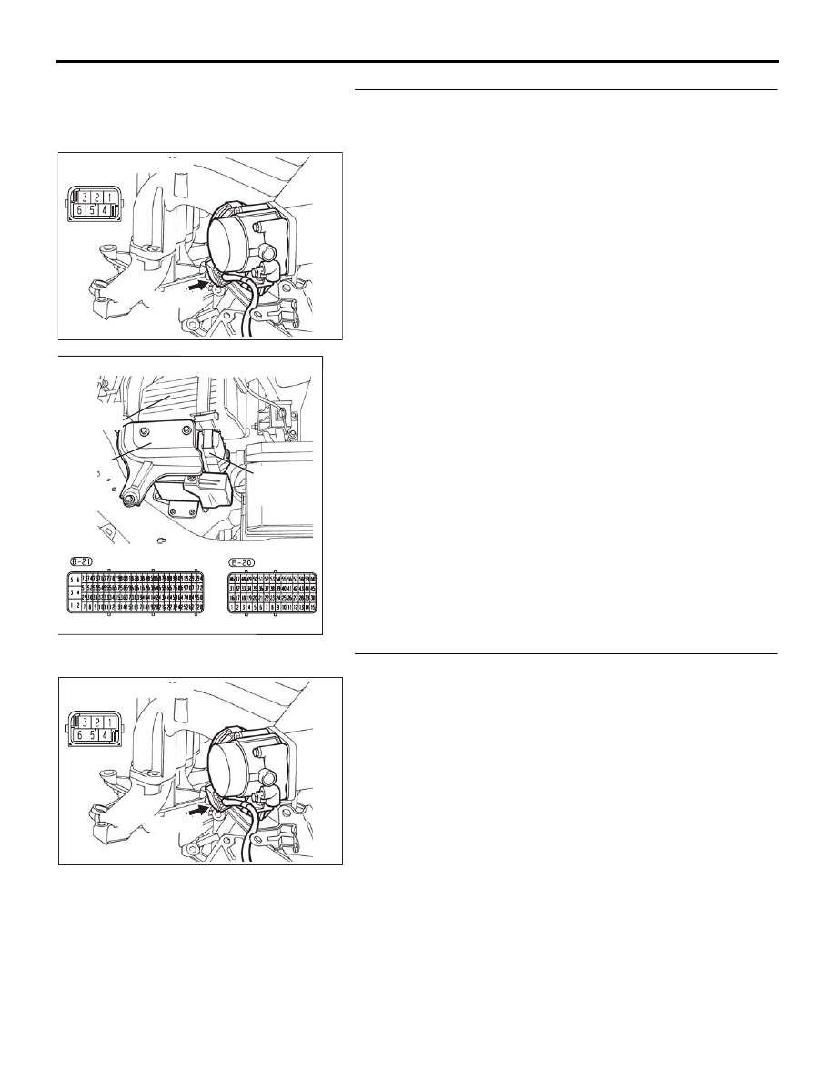
STEP 6. Check for short circuit to 5-Volts and harness 
damage between throttle position sensor connector B-06 
(terminal No. 5) and ECU connector B-20 (terminal No. 57).
Q: Is the harness wire in good condition?

YES : Go to Step 7.
NO :  Repair or repalce it. Then go to Step 8.

STEP 7. Replace the throttle body assembly.
(1) Replace the throttle body assembly.
(2) Turn the ignition switch to the "ON" position.
(3) After the DTC has been deleted, read the DTC again.
(4) Turn the ignition switch to the "LOCK" (OFF) position.

Q: Is DTC P0223 set?

YES : Retry the troubleshooting.
NO :  The inspection is complete.

03DB180A

CONNECTOR: B-06

B-06 (B)

16DB400A

COVER

ENGINE

CONTROL

UNIT

AIR

CLEANER

03DB180A

CONNECTOR: B-06

B-06 (B)

MULTIPORT FUEL INJECTION (MFI) DIAGNOSIS

MULTIPORT FUEL INJECTION (MFI)

13A-329

STEP 8. Using diagnostic tool , read the diagnostic trouble 
code (DTC).

CAUTION

To prevent damage to diagnostic tool , always turn the 
ignition switch to the "LOCK"(OFF) position before con-
necting or disconnecting diagnostic tool .
(1) Connect diagnostic tool to the data link connector.
(2) Turn the ignition switch to the "ON" position.
(3) After the DTC has been deleted, read the DTC again.
(4) Turn the ignition switch to the "LOCK"(OFF) position.

Q: Is DTC P0223 set?

YES : Retry the troubleshooting.
NO :  The inspection is complete.

00DB076A

MB991910

DATA LINK

CONNECTOR

MB991824

MB991827

MULTIPORT FUEL INJECTION (MFI) DIAGNOSIS

MULTIPORT FUEL INJECTION (MFI)

13A-330

DTC P0300: Random/Multiple Cylinder Misfire Detected 

.

TECHNICAL DESCRIPTION

• If a misfire occurs while the engine is running, the 

engine speed changes for an instant.

• The ECU checks for such changes in engine 

speed.

.

DTC SET CONDITIONS

Check Conditions

• Engine speed is beween idle and 6200 r/min.

• Engine torque is above 0.

• Engine speed during start is above 530 r/min. 

• Ignition counter (starts when engine speed 530 

r/min is exceeded) is above 6.

• Torque intervention by traction control is not 

active.

• Safety fuel cut off is not active.

• A/C compressor switching is not active. <M/T>

• Clutch pedal is not pressed. <M/T>.

Judgement Criteria (change in the angular accel-

eration of the crankshaft is used for misfire 
detection).

• MIL activated after 2 drive cycles.

• No Limp home.

• If MIL "blinks" in 1 Hz frequency, then there has 

been possible catalyst damage caused by the 
misfire.

.

EOBD DRIVE CYCLE PATTERN

Refer to Diagnostic Function 

− EOBD Drive Cycle 

P.13A-11

.

.

TROUBLESHOOTING HINTS (The most 
likely causes for this code to be set are:)

• Ignition system related part(s) failed.

• Poor crankshaft position sensor.

• Incorrect air/fuel ratio.

• Low compression pressure.

• Timing belt mialignment.

• Leaking vacuum hose connection
• ECU failed.

• Refer to component locations GROUP-

70

• Refer to configuration diagrams GROUP-

80

• Refer to circuit diagrams GROUP-

90

DIAGNOSIS

Required Special Tools:

• Diagnostic Tool (MUT-III Sub Assembly)

• MB991824: V.C.I.

• MB991827: USB Cable

• MB991910: Main Harness A

MULTIPORT FUEL INJECTION (MFI) DIAGNOSIS

MULTIPORT FUEL INJECTION (MFI)

13A-331

STEP 1. Using diagnostic tool , check data list item 02: 
Crank Angle Sensor.

CAUTION

To prevent damage to diagnostic tool , always turn the 
ignition switch to the "LOCK" (OFF) position before con-
necting or disconnecting diagnostic tool .
(1) Connect diagnostic tool to the data link connector.
(2) Start the engine and run at idle.
(3) Set diagnostic tool to the data reading mode for item 02, 

Crankshaft Angle Sensor.

(4) Check the waveform of the crankshaft position sensor while 

keeping the engine speed constant.

• The pulse width should be constant.

Q: Is the sensor operating properly?

YES : Go to Step 2.
NO :  Refer to, DTC P0335 

− Crankshaft Position Sensor 

Circuit Malfunction. 

P.13A-354

STEP 2. Using diagnostic tool , check data list item 28 
<bank 1> and 29 <bank2>: Short-Term Fuel Trim.
(1) Start the engine and run at idle.
(2) Set diagnostic tool to the data reading mode for item 

28<bank 1> and 29 <bank2>, Short-Term Fuel Trim.

• The fuel trim should be between −7.0 and +7.0 percent 

when the load is 2,500 r/min (during closed loop) after 
the engine is warmed.

Q: Is the specification normal?

YES : Go to Step 3.
NO :  Refer to:

DTC P0171 

− System too Lean (bank 1) 

P.13A-264

DTC P0172 

− System too Rich (bank 1) 

P.13A-266

DTC P0174 

− System too Lean (bank 2) 

P.13A-268

DTC P0175 

− System too Rich (bank 2) 

P.13A-270

.

00DB076A

MB991910

DATA LINK

CONNECTOR

MB991824

MB991827

00DB076A

MB991910

DATA LINK

CONNECTOR

MB991824

MB991827


Content   ..  557  558  559  560   ..