Mitsubishi 380. Manual - part 548


  Index      Mitsubishi     Mitsubishi 380 - service repair manual 2005 year


Search            


Content   ..  546  547  548  549   ..


Mitsubishi 380. Manual - part 548


MULTIPORT FUEL INJECTION (MFI) DIAGNOSIS

MULTIPORT FUEL INJECTION (MFI)

13A-284

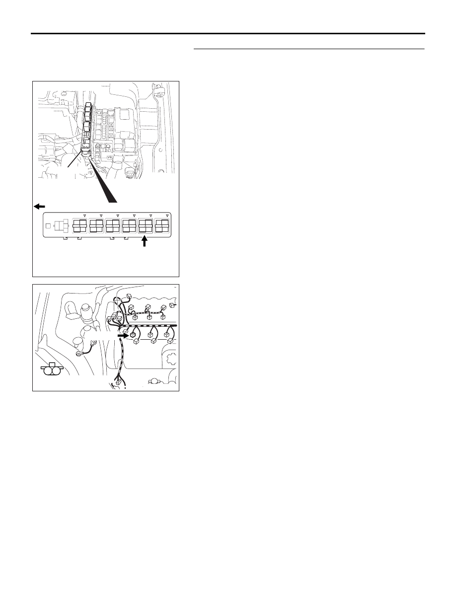
STEP 6. Check for harness damage between MFI relay 
connector B-17X (terminal No.4) and No. 2 cylinder injector 
connector B-30.
Q: Is the harness wire in good condition?

YES : Go to Step 7.
NO :  Repair it. Then go to Step 10.

1

2

3

4

AK303017

CONNECTOR: B-17X

FRONT OF VEHICLE

B-17X

AB

HARNESS

CONNECTOR:

COMPONENT SIDE

RELAY BOX

AK303103

M

1

2

CONNECTOR: B-30

B-30 (GR)

HARNESS CONNECTOR:

COMPONENT SIDE

AB

MULTIPORT FUEL INJECTION (MFI) DIAGNOSIS

MULTIPORT FUEL INJECTION (MFI)

13A-285

STEP 7. Check harness connector B-20 at ECU for 
damage.
Q: Is the connector in good condition?

YES : Go to Step 8.
NO :  Repair or replace it. Refer to GROUP 00E, Harness 

Connector Inspection 

P.00E-2

. Then go to Step 10.

STEP 8. Check for open circuit and short circuit to ground 
and harness damage between No.2 cylinder injector 
connector B-30 (terminal No. 2) and ECU connector B-20 
(terminal No. 04).
Q: Is the harness wire in good condition?

YES : Go to Step 9.
NO :  Repair it. Then go to Step 10.

16DB400A

COVER

ENGINE

CONTROL

UNIT

AIR

CLEANER

AK303103

M

1

2

CONNECTOR: B-30

B-30 (GR)

HARNESS CONNECTOR:

COMPONENT SIDE

AB

16DB400A

COVER

ENGINE

CONTROL

UNIT

AIR

CLEANER

MULTIPORT FUEL INJECTION (MFI) DIAGNOSIS

MULTIPORT FUEL INJECTION (MFI)

13A-286

STEP 9. Using the oscilloscope, check the No.2 cylinder 
injector.
(1) Disconnect the No. 2 cylinder injector connector B-30 and 

connect the test harness special tool (MB991658) between 
the separated connectors. (All terminals should be 
connected)

(2) Connect the oscilloscope probe to the injector side 

connector terminal No. 2.

NOTE: When measuring with the ECU side connector, dis-
connect the all ECU connectors and connect check harness 
special tool (MB992044) between the separated connec-
tors. Then connect an oscilloscope probe to the check har-
ness connector terminal No. 04.

(3) Start the engine and run at idle.

(4) Measure the waveform.

• The waveform should show a normal pattern similar to 

the illustration.

(5) Turn the ignition switch to the "LOCK" (OFF) position.

Q: Is the waveform normal?

YES : It can be assumed that this malfunction is intermittent. 

Refer to GROUP 00, How to Use 
Troubleshooting/Inspection Service Points 

− How to 

Cope with Intermittent Malfunctions 

P.00-14

.

NO :  Replace the ECU. Then go to Step 10.

STEP 10. Test the EOBD drive cycle.
(1) Carry out a test drive with the drive cycle pattern. Refer to 

Diagnostic Function 

− EOBD Drive Cycle −

P.13A-11

.

(2) Check the diagnostic trouble code (DTC).

Q: Is DTC P0202 set?

YES : Retry the troubleshooting.
NO :  The inspection is complete.

AK303103

M

1

2

CONNECTOR: B-30

B-30 (GR)

HARNESS CONNECTOR:

COMPONENT SIDE

AB

AK302166

1 2

INJECTOR

CONNECTOR

MB991658

OSCILLOSCOPE

AB

AKX01557 AB

A

NORMAL  WAVEFORM

A:INJECTOR DRIVE TIME

MULTIPORT FUEL INJECTION (MFI) DIAGNOSIS

MULTIPORT FUEL INJECTION (MFI)

13A-287

DTC P0203: Injector Circuit Malfunction - Cylinder 3.

.

CIRCUIT OPERATION

• Refer to DTC P0300 - Random/Multiple Misfire- 

P.13A-330

 and Misfire Cylinder 3- 

P.13A-338

.

• The injector power is supplied from the MPI relay 

(terminal No. 4).

• The ECU controls the injector by turning the 

power transistor in the ECU "ON" and "OFF".

.

TECHNICAL DESCRIPTION

• The amount of fuel injected by the injector is con-

trolled by the amount of continuity time the coil is 
grounded by the ECU.

• A surge voltage is generated when the injectors 

are switched on/off.

• The ECU monitors this surge voltage.

.

DTC SET CONDITIONS <Circuit continuity 

 open circuit and shorted low>

Check Conditions

• Battery voltage is between 9.04 and 16.01vols.

• Engine speed is above 801 r/min.

Judgment Criteria

• IC internal test (open circuit, short to earth, short 

to battery). 

• MIL on after 2 drive cycles.

• Misfire present.

.

EOBD DRIVE CYCLE PATTERN

Refer to Diagnostic Function 

− EOBD Drive Cycle − 

P.13A-11

.

.

AK303106

CONNECTOR: B-03

AB

B-03 (GR)

1

2

3

4

1

2

3

4

1

2

3

4

1

2

3

4

AK303014

CONNECTOR: B-17X

MFI RELAY

MFI RELAY

FRONT OF VEHICLE

B-17X

AB

AK303097

CONNECTOR: B-32

AB

B-32 (B)

16DB400A

COVER

ENGINE

CONTROL

UNIT

AIR

CLEANER


Content   ..  546  547  548  549   ..