Mitsubishi 380. Manual - part 547
MULTIPORT FUEL INJECTION (MFI) DIAGNOSIS
MULTIPORT FUEL INJECTION (MFI)
13A-280
DTC P0202: Injector Circuit Malfunction - Cylinder 2.
.
CIRCUIT OPERATION
• Refer to DTC P0300 - Random/Multiple Misfire-
and Misfire Cylinder 2-
.
• The injector power is supplied from the MPI relay
(terminal No. 4).
• The ECU controls the injector by turning the
power transistor in the ECU "ON" and "OFF".
.
TECHNICAL DESCRIPTION
• The amount of fuel injected by the injector is con-
trolled by the amount of continuity time the coil is
grounded by the ECU.
• A surge voltage is generated when the injectors
are switched on/off.
• The ECU monitors this surge voltage.
.
DTC SET CONDITIONS <Circuit continuity
− open circuit and shorted low>
Check Conditions
• Battery voltage is between 9.04 and 16.01vols.
• Engine speed is above 801 r/min.
Judgment Criteria
• IC internal test (open circuit, short to earth, short
to battery).
• MIL on after 2 drive cycles.
• Misfire present.
.
EOBD DRIVE CYCLE PATTERN
Refer to Diagnostic Function
− EOBD Drive Cycle
.
.
AK303102
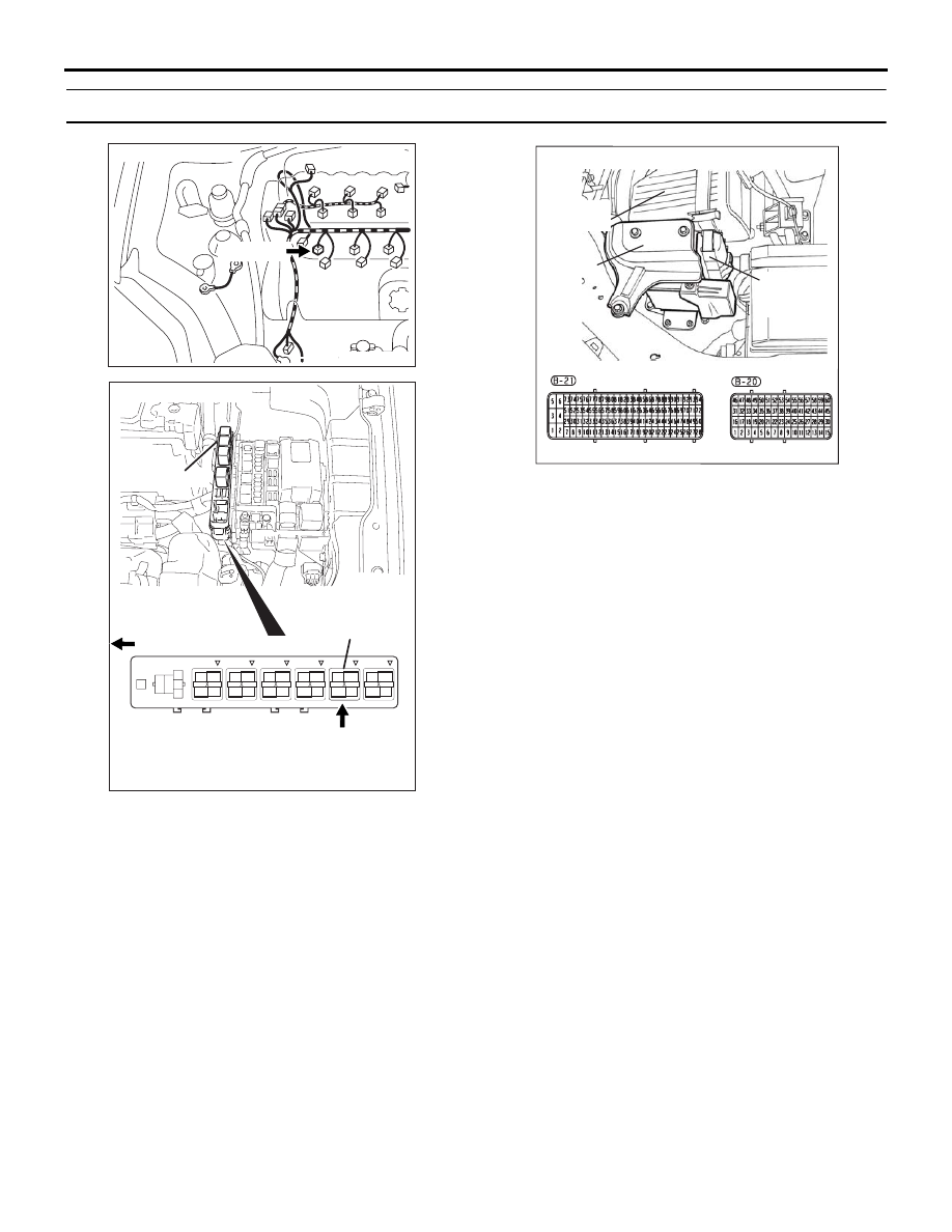
CONNECTOR: B-30
B-30 (GR)
AB
1
2
3
4
1
2
3
4
1
2
3
4
1
2
3
4
AK303014
CONNECTOR: B-17X
MFI RELAY
MFI RELAY
FRONT OF VEHICLE
B-17X
AB
16DB400A
COVER
ENGINE
CONTROL
UNIT
AIR
CLEANER