Mitsubishi 380. Manual - part 546


  Index      Mitsubishi     Mitsubishi 380 - service repair manual 2005 year


Search            


Content   ..  544  545  546  547   ..


Mitsubishi 380. Manual - part 546


MULTIPORT FUEL INJECTION (MFI) DIAGNOSIS

MULTIPORT FUEL INJECTION (MFI)

13A-276

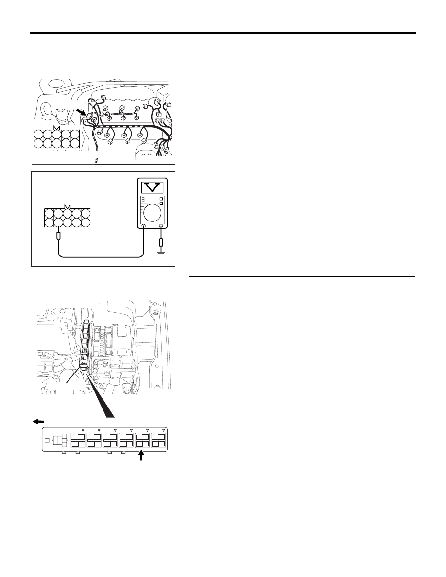
STEP 6. Measure the power supply voltage at intermediate 
connector B-32.
(1) Disconnect the connector B-32 and measure at the female 

connector side.

(2) Turn the ignition switch to the "ON" position.

(3) Measure the voltage between terminal No. 9 and ground.

• Voltage should be battery positive voltage.

(4) Turn the ignition switch to the "LOCK" (OFF) position.

Q: Is battery positive voltage (approximately 12 volts) 

present?
YES : 
Go to Step 8.
NO :  Go to Step 7.

STEP 7. Check harness connector B-17X at MFI relay for 
damage.
Q: Is the harness connector in good condition?

YES : Repair harness wire between MFI relay connector 

B-17X (terminal No. 4) and intermediate connector 
B-32 (terminal No. 9) because of open circuit or short 
circuit to ground. Then go to Step 12.

NO :  Repair or replace it. Refer to GROUP 00E, Harness 

Connector Inspection 

P.00E-2

. Then go to Step 12.

AK303053

3

4

5

8

9

1

2

6

7

10

CONNECTOR: B-32

HARNESS CONNECTOR:

COMPONENT SIDE

AB

B-32 (B)

3

4

5

8

9

1

2

6

7

10

AK203172

B-32 HARNESS 

CONNECTOR: 

COMPONENT

SIDE

AB

1

2

3

4

AK303017

CONNECTOR: B-17X

FRONT OF VEHICLE

B-17X

AB

HARNESS

CONNECTOR:

COMPONENT SIDE

RELAY BOX

MULTIPORT FUEL INJECTION (MFI) DIAGNOSIS

MULTIPORT FUEL INJECTION (MFI)

13A-277

STEP 8. Check for harness damage between MFI relay 
connector B-17X (terminal No. 4) and intermediate 
connector B-32 (terminal No. 9).
Q: Is the harness wire in good condition?

YES : Go to Step 9.
NO :  Repair it. Then go to Step 12.

1

2

3

4

AK303017

CONNECTOR: B-17X

FRONT OF VEHICLE

B-17X

AB

HARNESS

CONNECTOR:

COMPONENT SIDE

RELAY BOX

AK303053

3

4

5

8

9

1

2

6

7

10

CONNECTOR: B-32

HARNESS CONNECTOR:

COMPONENT SIDE

AB

B-32 (B)

MULTIPORT FUEL INJECTION (MFI) DIAGNOSIS

MULTIPORT FUEL INJECTION (MFI)

13A-278

STEP 9. Check harness connector B-20 at ECU for 
damage.
Q: Is the harness connector in good condition?

YES : Go to Step 10.
NO :  Repair or replace it. Refer to GROUP 00E, Harness 

Connector Inspection 

P.00E-2

. Then go to Step 12.

STEP 10. Check for open circuit and short circuit to 
ground and harness damage between intermediate 
connector B-32 (terminal No. 5) and ECU connector B-20 
(terminal No. 03).
Q: Is the harness wire in good condition?

YES : Go to Step 11.
NO :  Repair it. Then go to Step 12.

16DB400A

COVER

ENGINE

CONTROL

UNIT

AIR

CLEANER

AK303053

3

4

5

8

9

1

2

6

7

10

CONNECTOR: B-32

HARNESS CONNECTOR:

COMPONENT SIDE

AB

B-32 (B)

16DB400A

COVER

ENGINE

CONTROL

UNIT

AIR

CLEANER

MULTIPORT FUEL INJECTION (MFI) DIAGNOSIS

MULTIPORT FUEL INJECTION (MFI)

13A-279

STEP 11. Using the oscilloscope, check the No. 1 cylinder 
injector.
(1) Disconnect the intermediate connector B-32 and connect 

the test harness MB991658 between the separated 
connectors.

(2) Connect the oscilloscope probe to injector intermediate 

connector terminal to No.5.

NOTE: When measuring with the ECU side connector, dis-
connect the all ECU connectors and connect check harness 
special tool (MB992044) between the separated connec-
tors. Then connect an oscilloscope probe to the check har-
ness connector terminal No.03.

(3) Start the engine and run at idle.

(4) Measure the waveform.

• The waveform should show a normal pattern similar to 

the illustration.

(5) Turn the ignition switch to the "LOCK" (OFF) position.

Q: Is the waveform normal?

YES : It can be assumed that this malfunction is intermittent. 

Refer to 00, How to Use Troubleshooting/Inspection 
Service Points 

− How to Cope with Intermittent 

Malfunctions 

P.00-14

.

NO :  Replace the ECU. Then go to Step 12.

STEP 12. Test the EOBD drive cycle.
(1) Carry out a test drive with the drive cycle pattern. Refer to 

Diagnostic Function 

− EOBD Drive Cycle −

P.13A-11

.

(2) Check the diagnostic trouble code (DTC).

Q: Is DTC P0201 set?

YES : Retry the troubleshooting.
NO :  The inspection is complete.

AK303053

3

4

5

8

9

1

2

6

7

10

CONNECTOR: B-32

HARNESS CONNECTOR:

COMPONENT SIDE

AB

B-32 (B)

1 2 3
6 7 8

4 5
9 10

AK203300

OSCILLOSCOPE

MB991658

B-32 INTERMEDIATE

CONNECTOR

AB

AKX01557 AB

A

NORMAL  WAVEFORM

A:INJECTOR DRIVE TIME


Content   ..  544  545  546  547   ..