Mitsubishi 380. Manual - part 472
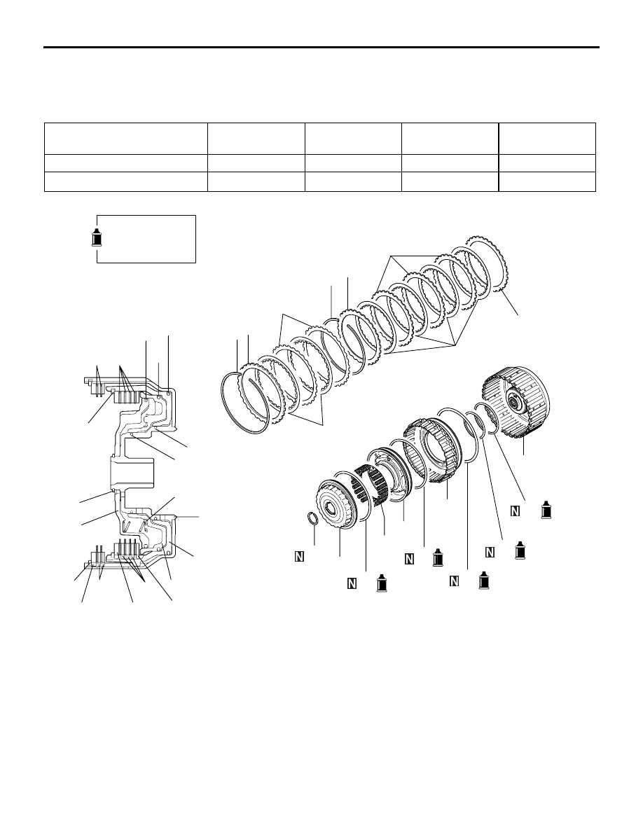
REVERSE AND OVERDRIVE CLUTCH
AUTOMATIC TRANSMISSION OVERHAUL
23B-48
REVERSE AND OVERDRIVE CLUTCH
DISASSEMBLY AND REASSEMBLY
M1233021200256
Number of clutch discs and plates
Pressure plate
Clutch disc
Clutch plate
Clutch reaction
plate
Over drive clutch
1
4
3
1
Reverse clutch
−
2
2
1
AKX01127AE
Apply automatic
transmission fluid
to all moving parts
before installation.
13
10
15
11
12
14
6
8
3
2
2
1
9
5
4
7
19
18
20
16
9
8
6
1
17
3
7
18
10
11
19
13
20
16
17
15
14
12
5
Disassembly steps
>>
G
<<
1.
Snap ring
>>
F
2.
Clutch reaction plate
>>
F
3.
Clutch disc
>>
F
4.
Clutch plate
>>
E
5.
Snap ring
>>
D
<<
6.
Clutch reaction plate
>>
D
<<
7.
Clutch disc
>>
D
<<
8.
Clutch plate
>>
D
<<
9.
Pressure plate
<<
A
>>
>>
C
<<
10. Snap ring
11. Spring retainer
>>
A
12. D-ring
13. Return spring
14. Overdrive clutch piston
>>
A
15. D-ring
>>
B
16. Reverse clutch piston
>>
A
17. D-ring
>>
A
18. D-ring
>>
A
19. D-ring
20. Reverse clutch retainer
Disassembly steps ( つづき )