Mitsubishi 380. Manual - part 470


  Index      Mitsubishi     Mitsubishi 380 - service repair manual 2005 year


Search            


Content   ..  468  469  470  471   ..


Mitsubishi 380. Manual - part 470


AK501914

TRANSMISSION

AUTOMATIC TRANSMISSION OVERHAUL

23B-40

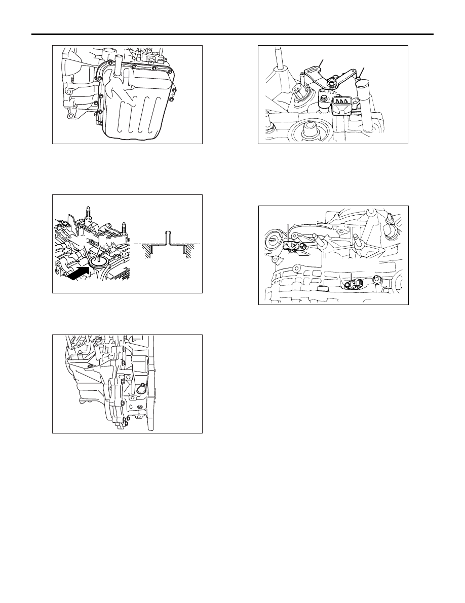
88.Install the valve body cover, and then tighten its 

mounting bolts to the specified torque of 11 

± 1 

N

⋅m.

AK203140 AE

A

A

B

B

89.Press Face  "A" of the air breather to be on the 

same plane as the Face "B" of the transmission 
case as shown in the illustration.

AK300220

90.Install the sealing cap and tighten the bolt to the 

specified torque of 5.0 

± 1.0 N⋅m. <Type with 

sealing cap>

AK202096

Manual control lever

Inhibitor switch

AB

91.Install the inhibitor switch and tighten the bolt to 

the specified torque of 11 

± 1 N⋅m.

92.Install the manual control lever and tighten the nut 

to the specified torque of 22 

± 3 N⋅m.

AK202095AB

Output shaft 

speed sensor

Input shaft 

speed sensor

93.Install the input shaft speed sensor and output 

shaft speed sensor and tighten the bolt to the 
specified torque of 11 

± 1 N⋅m.

94.Apply ATF on the both sides of the new gasket 

and threads of the eyebolts, and then tighten to 
the specified torque of 24 

± 3 N⋅m.

95.Tighten the oil cooler feed pipe clamp bolt to the 

specified torque of 11 

± 1 N⋅m.

96.Install the oil dipstick.

97.Install the control cable support brackets to the 

specified torque of 23 

± 3 N⋅m.

98.Install the harness bracket to the specified torque 

of 11 

± 1 N⋅m.

99.Install the roll stopper brackets to the specified 

torque of 70 

± 10 N⋅m.

AK301263AC

A

TRANSMISSION

AUTOMATIC TRANSMISSION OVERHAUL

23B-41

CAUTION

Apply ATF to the oil pump drive hub before 
installing the torque converter. Be careful not to 
damage the oil seal lip when installing the torque 
converter.
100.Install the torque converter, and align it with the 

oil pump so that the shown dimension "A" meets 
the reference value.

Reference value: Approximately 9.4 mm

ADJUSTMENT OF TRANSMISSION

M1233030400098

THRUST WASHER SELECTION FOR 
ADJUSTMENT OF INPUT SHAFT END 
PLAY

<Measurement using Solder>

CAUTION

• If the solder is not available, select the thrust 

washer in accordance with Plastigage 
method.

• If the thrust washer appropriate for the stand-

ard value cannot be selected using the solder, 
select the thrust washer in accordance with 
Plastigage method.

AK301756

Input shaft

Two beads

of solder

Underdrive

clutch retainer

AC

1. Put the solders (1.0 mm diameter, about 10 mm 

long) in the illustrated positions of the underdrive 
clutch retainer.

2. Install the adjusting thrust washer having 

minimum thickness.

AK301247AB

MD998412

CAUTION

Never use a gasket that has been tightened.

3. Use the special tool Guide (MD998412) to install a 

new oil pump gasket and the oil pump. Tighten the 
oil pump mounting bolts to the specified torque of 
29 

± 2 N⋅m.

4. Remove the oil pump mounting bolts.

AK300236AC

MD998333

5. Using special tools Oil pump remover 

(MD998333) remove the oil pump and then take 
out the crushed solders.

6. If the solders have not crushed, use thicker thrust 

washer and repeat steps 3 to 5.

AK301249

7. Use a micrometer to measure the thickness of the 

crushed solder beads and record the measured 
value.

8. Select the thrust washer, calculated by the 

following formula, in the table.

T = T1 + T2
T: Clearance mm
T1: The crushed solder thickness mm

TRANSMISSION

AUTOMATIC TRANSMISSION OVERHAUL

23B-42

T2: The thrust washer thickness used for 

measurement mm 

Available thrust washer

Clearance mm 
(T)

Thickness mm Identification 

mark

2.25 

− 2.45

1.8

18

2.45 

− 2.65

2.0

20

2.65 

− 2.85

2.2

22

2.85 

− 3.05

2.4

24

3.05 

− 3.25

2.6

26

3.25 

− 3.45

2.8

28

<Measurement using Plastigage>

AK301756

Input shaft

Two beads

of plastigage

Underdrive

clutch retainer

AE

1. Put the plastigage (about 10 mm long) in the 

illustrated positions of the underdrive clutch 
retainer.

2. Install the adjusting thrust washer having the 

minimum thickness.

AK301247AB

MD998412

CAUTION

Never use a gasket that has been tightened.

3. Use the special tool Guide (MD998412) to install a 

new oil pump gasket and the oil pump. Tighten the 
oil pump mounting bolts to the specified torque of 
29 

± 2 N⋅m.

4. Remove the oil pump mounting bolts.

AK300236AC

MD998333

5. Using special tools Oil pump remover 

(MD998333) to remove the oil pump and then 
take out the crushed plastigages.

6. If the plastigages have not crushed, use thicker 

adjusting thrust washer and repeat steps 3 to 5.

AK402081

Plastigage

Thrust washer

AG

7. Measure the width of the crushed plastigage at its 

widest part using a scale printed on the plastigage 
package.

8. Select the thrust washer, calculated by the 

following formula, in the table.

T = T3 + T2
T: Clearance mm
T3: The crushed plastigage thickness mm
T2: The thrust washer thickness used for 

measurement mm

Available thrust washer

Clearance mm 
(T)

Thickness mm Identification 

mark

2.25 

− 2.45

1.8

18

2.45 

− 2.65

2.0

20

2.65 

− 2.85

2.2

22

2.85 

− 3.05

2.4

24

3.05 

− 3.25

2.6

26

3.25 

− 3.45

2.8

28

TRANSMISSION

AUTOMATIC TRANSMISSION OVERHAUL

23B-43

SPACER SELECTION FOR ADJUST-
MENT OF DIFFERENTIAL CASE 
PRELOAD

<Measurement using Solder>

CAUTION

• If the solder is not available, select the spacer 

in accordance with Plastigage method.

• If the spacer appropriate for the standard 

value cannot be selected using the solder, 
select the spacer in accordance with Plasti-
gage method.

AK301758AD

Two beads 

of solder

1. Put the solders (1.0 mm diameter, about 10 mm 

long) in the illustrated positions of the converter 
housing.

AK202226

MB991445

AB

2. Use the special tools Bush remover and installer 

(MB991445) to press the differential bearing outer 
race into the torque converter housing.

AK202103

3. Install the converter housing on the transmission 

case without applying FIPG. Tighten the mounting 
bolts to the specified torque of 48 

± 6 N⋅m.

4. Remove the bolts and converter housing, and 

take out the solder pieces.

5. If the solders have not crushed, use thicker the 

solders (1.6 mm diameter, about 10 mm long) and 
repeat steps 2 to 4.

AK301249

6. Measure the thickness of the crushed solder with 

a micrometer, and then select a spacer that will 
provide the standard value.

Spacer thickness: (T1 

 0.045 mm) to (T1  

0.105 mm)
T1: The crushed solder thickness mm

Standard value: 0.045 

 0.105 mm

<Measurement using Plastigage>

AK400083

Plastigage

AC

1. Put the plastigage (about 10 mm long) in the 

illustrated positions of the converter housing.

2. Install the adjusting spacer having the minimum 

thickness.


Content   ..  468  469  470  471   ..