Mitsubishi 380. Manual - part 386


  Index      Mitsubishi     Mitsubishi 380 - service repair manual 2005 year


Search            


Content   ..  384  385  386  387   ..


Mitsubishi 380. Manual - part 386


AUTOMATIC TRANSMISSION DIAGNOSIS

AUTOMATIC TRANSMISSION

23A-84

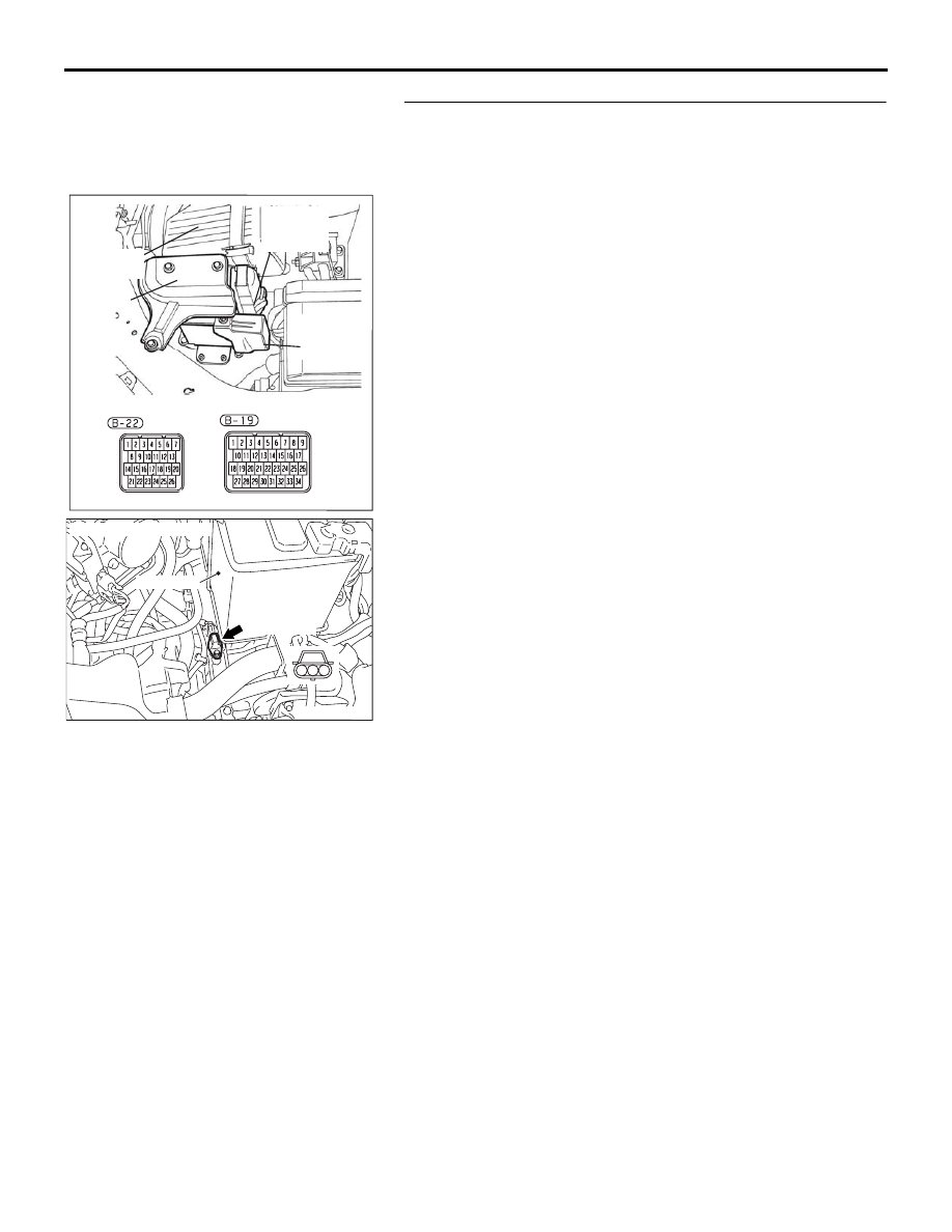
STEP 13. Check A/T-ECU connector B-22 and output shaft 
speed sensor connector B-107 for loose, corroded or 
damaged terminals, or terminals pushed back in the 
connector.
Q: Are the connectors and terminals in good condition?

YES : Go to Step 14.
NO :  Repair or replace the damaged components. Refer to 

GROUP 00E, Harness Connector Inspection 

P.00E-2

.

16DB480A

COVER

ENGINE

CONTROL

UNIT

AIR

CLEANER

A/T

CONTROL

UNIT

AC305353AC

CONNECTOR: B-107

BATTERY

B-107 (GR)

3

2

1

AUTOMATIC TRANSMISSION DIAGNOSIS

AUTOMATIC TRANSMISSION

23A-85

STEP 14. Check the harness for open circuit or damage 
between A/T-ECU connector B-22 terminal 12 and output 
shaft speed sensor connector B-107 terminal 1.
Q: Is the harness wire in good condition?

YES : Go to Step 16.
NO :  Repair or replace the harness wire.

STEP 15. Check A/T-ECU connector B-22 for loose, 
corroded or damaged terminals, or terminals pushed back 
in the connector.
Q: Are the connector and terminals in good condition?

YES : Replace the A/T-ECU.
NO :  Repair or replace the damaged components. Refer to 

GROUP 00E, Harness Connector Inspection 

P.00E-2

.

16DB480A

COVER

ENGINE

CONTROL

UNIT

AIR

CLEANER

A/T

CONTROL

UNIT

AC305353AC

CONNECTOR: B-107

BATTERY

B-107 (GR)

3

2

1

16DB480A

COVER

ENGINE

CONTROL

UNIT

AIR

CLEANER

A/T

CONTROL

UNIT

AUTOMATIC TRANSMISSION DIAGNOSIS

AUTOMATIC TRANSMISSION

23A-86

STEP 16. Using the oscilloscope, check the output shaft 
speed sensor waveform at A/T-ECU connectors B-22 by 
using check harness special tool MB992045.
(1) Disconnect all the connectors from the A/T-ECU.

(2) Connect special tool MB992045 (check harness) between 

the A/T-ECU and the body-side harness connector.

(3) Connect an oscilloscope probe to A/T-ECU connector B-22 

terminal 11 and 12.

(4) Start the engine and drive the vehicle at constant speed of 

50 km/h  (Gear range: 3rd gear).

16DB480A

COVER

ENGINE

CONTROL

UNIT

AIR

CLEANER

A/T

CONTROL

UNIT

10DB161A

A/T-ECU CHECK HARNESS
    MB992045

A/T-ECU

A/T-ECU CHECK 
HARNESS
CONNECTORS

10DB090A

B-22 CONNECTOR: 

OSCILLO-
SCOPE

PROBE

AUTOMATIC TRANSMISSION DIAGNOSIS

AUTOMATIC TRANSMISSION

23A-87

(5) Check the output shaft speed sensor waveform.

• The output shaft speed sensor waveform should show a 

pattern similar to the illustration. The maximum value 
should be 4.8 volts or more and the minimum value 0.8 
volt or less. The output waveform should not contain 
electrical noise.

(6) Turn the ignition switch to the "LOCK" (OFF) position.

Q: Is the waveform normal?

YES : Go to Step 19.
NO :  Go to Step 17.

STEP 17. Replace the output shaft speed sensor.
(1) Replace the output shaft speed sensor. Refer to GROUP 

23B, Transmission 

P.23B-13

.

(2) Test drive the vehicle.
(3) Check for A/T diagnostic trouble code.

Q: Is A/T (P0720) set?

YES : Go to Step 18.
NO :  The procedure is complete.

STEP 18. Replace the transfer drive gear or driven gear.
(1) Replace the transfer drive gear or driven gear. Refer to 

GROUP 23B, Transmission 

P.23B-13

, Direct Planetary 

Carrier 

P.23B-57

.

(2) Test drive the vehicle.
(3) Check for A/T diagnostic trouble code.

Q: Is A/T (P0720) set?

YES : An A/T DTC may have set due to external radio 

frequency interference (RFI) possibility caused by 
cellular phone activity, or aftermarket components 
installed on the vehicle.

NO :  The procedure is complete.

ACX02131

NORMAL WAVEFORM

AD

(V)

5

0

AC305353AD

OUTPUT SHAFT
SPEEDB SENSOR

BATTERY

AC002221AC

TRANSFER
DRIVE GEAR

TRANSFER
DRIVEN GEAR


Content   ..  384  385  386  387   ..