Mitsubishi 380. Manual - part 384


  Index      Mitsubishi     Mitsubishi 380 - service repair manual 2005 year


Search            


Content   ..  382  383  384  385   ..


Mitsubishi 380. Manual - part 384


AUTOMATIC TRANSMISSION DIAGNOSIS

AUTOMATIC TRANSMISSION

23A-76

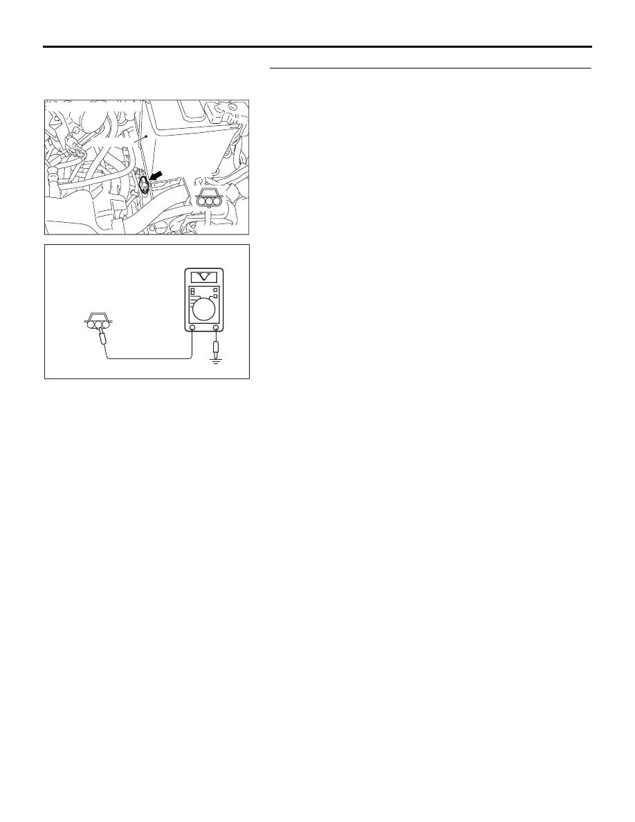
STEP 5. Measure the A/T-ECU to speed sensor output 
voltage at the output shaft speed sensor connector B-107.
(1) Disconnect connector B-107 from the speed sensor and 

measure voltage at the harness side.

(2) Turn the ignition switch to the "ON" position.

(3) Measure the voltage between terminal 2 and ground.

• The voltage should measure between 4.5 and 4.9 volts.

(4) Turn the ignition switch to the "LOCK" (OFF) position.

Q: Is the measured voltage between 4.5 and 4.9 volts?

YES : Go to Step 11.
NO :  Go to Step 6.

AC305353AC

CONNECTOR: B-107

BATTERY

B-107 (GR)

3

2

1

3 2 1

AC210662

B-107 HARNESS
CONNECTOR:
COMPONENT SIDE

AB

AUTOMATIC TRANSMISSION DIAGNOSIS

AUTOMATIC TRANSMISSION

23A-77

STEP 6. Measure the A/T-ECU output voltage to the speed 
sensor at the A/T-ECU connector B-22 by using check 
harness special tool MB992045.
(1) Disconnect all the connectors from the A/T-ECU.

(2) Connect special tool MB992045 (check harness) between 

the A/T-ECU and the body-side harness connector.

(3) Turn the ignition switch to the "ON" position.

(4) Measure the voltage between connector B-22 (terminal 11) 

and ground.

• The voltage should measure between 4.5 and 4.9 volts.

(5) Turn the ignition switch to the "LOCK" (OFF) position.

Q: Is the measured voltage between 4.5 and 4.9 volts?

YES : Go to Step 7.
NO :  Go to Step 9.

16DB480A

COVER

ENGINE

CONTROL

UNIT

AIR

CLEANER

A/T

CONTROL

UNIT

10DB161A

A/T-ECU CHECK HARNESS
    MB992045

A/T-ECU

A/T-ECU CHECK 
HARNESS
CONNECTORS

10DB089A

B-22  CONNECTOR:

AUTOMATIC TRANSMISSION DIAGNOSIS

AUTOMATIC TRANSMISSION

23A-78

STEP 7. Check A/T-ECU connector B-22 and output shaft 
speed sensor connector B-107 for loose, corroded or 
damaged terminals, or terminals pushed back in the 
connector.
Q: Are the connectors in good condition?

YES : Go to Step 8.
NO :  Repair or replace the damaged components. Refer to 

GROUP 00E, Harness Connector Inspection 

P.00E-2

.

16DB480A

COVER

ENGINE

CONTROL

UNIT

AIR

CLEANER

A/T

CONTROL

UNIT

AC305353AC

CONNECTOR: B-107

BATTERY

B-107 (GR)

3

2

1

AUTOMATIC TRANSMISSION DIAGNOSIS

AUTOMATIC TRANSMISSION

23A-79

STEP 8. Check the harness for open circuit or damage 
between A/T-ECU connector B-22 terminal 11 and output 
shaft speed sensor connector B-107 terminal 2.
Q: Is the harness wire in good condition?

YES : Go to Step 19.
NO :  Repair or replace the harness wire.

16DB480A

COVER

ENGINE

CONTROL

UNIT

AIR

CLEANER

A/T

CONTROL

UNIT

AC305353AC

CONNECTOR: B-107

BATTERY

B-107 (GR)

3

2

1


Content   ..  382  383  384  385   ..