Mitsubishi 380. Manual - part 294


  Index      Mitsubishi     Mitsubishi 380 - service repair manual 2005 year


Search            


Content   ..  292  293  294  295   ..


Mitsubishi 380. Manual - part 294


BASIC BRAKE SYSTEM DIAGNOSIS

BASIC BRAKE SYSTEM

35A-10

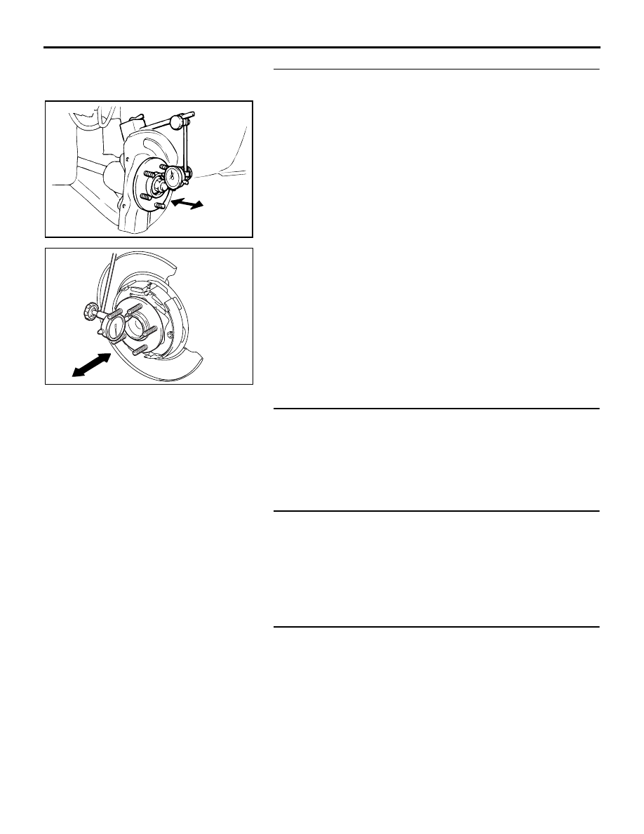
STEP 7. Check the wheel bearings for end play.
(1) Remove the brake discs.
(2) Place a dial gauge as shown, and measure the end play 

while moving the hub in the axial direction.

Limit: 0.05 mm (0.002 inch)

Q: Does the measured end play exceed the limit?

YES : Replace the faulty hub assembly. Then go to Step 10.
NO :  Go to Step 8.

STEP 8. Check whether the brake booster or master 
cylinder return is insufficient.

Q: Is the brake booster or master cylinder return 

insufficient?
YES : 
Replace the part. Then go to Step 10.
NO :  Go to Step 9.

STEP 9. Adjust the brake pedal or brake booster pushrod.
Refer to 

P.35A-13

 or 

P.35A-26

.

Q: Are the brake pedal and the brake booster pushrod 

adjusted correctly?
YES : 
Go to Step 10.
NO :  Adjust the brake pedal or the brake booster pushrod. 

Then go to Step 10.

STEP 10. Recheck symptom.

Q: Is the symptom eliminated?

YES : The procedure is complete.
NO :  Start over at step 1. If a new symptom surfaces, refer 

to the symptom chart.

AC102438 AC

<FRONT>

AC205869AC

<REAR>

BASIC BRAKE SYSTEM DIAGNOSIS

BASIC BRAKE SYSTEM

35A-11

INSPECTION PROCEDURE 8: Groaning, Clicking or Rattling Noise when Brakes are not Applied.

DIAGNOSIS

.

STEP 1. Check whether foreign material has entered the 
wheel covers.

Q: Is there any foreign material?

YES : Remove it. Then go to Step 5.
NO :  Go to Step 2.

STEP 2. Check for looseness of the wheel nuts.

Q: Are the wheel nuts loose?

YES : Tighten to 98 

± 10 N⋅m (73 ± 7 ft-lb). Then go to Step 

5 .

NO :  Go to Step 3.

STEP 3. Check for looseness of the caliper installation 
bolt.
Q: Is the caliper installation bolt loose?

YES : Tighten to 100 

± 10 N⋅m (74 ± 7 ft-lb) for the front 

caliper. Tighten to 60 

± 5 N⋅m (45 ± 3 ft-lb) for the rear 

caliper. Then go to Step 5.

NO :  Go to Step 4.

AC308605AB

<FRONT>

<REAR>

SPECIAL TOOLS

BASIC BRAKE SYSTEM

35A-12

STEP 4. Check the wheel bearings for end play.
(1) Remove the brake discs.
(2) Place a dial gauge as shown, and measure the end play 

while moving the hub in the axial direction.

Limit: 0.05 mm (0.002 inch)

Q: Does the measured end play exceed the limit?

YES : Replace the faulty hub assembly. Then go to Step 5.
NO :  Go to Step 5.

STEP 5. Recheck symptom.

Q: Is the symptom eliminated?

YES : The procedure is complete.
NO :  Start over at step 1. If a new symptom surfaces, refer 

to the symptom chart.

SPECIAL TOOLS

M1351000600360

AC102438 AC

<FRONT>

AC205869AC

<REAR>

TOOL

TOOL NUMBER AND 
NAME

SUPERSESSION

APPLICATION

MB991568
Push rod adjusting socket

General service 
tool

Adjustment of the brake booster 
push rod protrusion amount

MB990964
Brake tool set
A: MB990520
Disc brake piston expander

MB990620-01 or 
general service 
tool

Pushing-in of the disc brake 
piston

MB990964

A

B

ON-VEHICLE SERVICE

BASIC BRAKE SYSTEM

35A-13

ON-VEHICLE SERVICE

BRAKE PEDAL CHECK AND ADJUSTMENT

M1351000900446

BRAKE PEDAL HEIGHT

1. Turn up the carpet, etc. under the brake pedal.
2. Measure the brake pedal height as illustrated.

Standard value: 168..5 

 171.5 mm A/T

Standard value: 169.4  

 172.4 mm - M/T

[From the surface of dash panel to the face of pedal 
pad]

3. If the brake pedal height is not within the standard value, 

follow the procedure below.

(1) Disconnect the stoplight switch connector.
(2) Remove the brake booster (Refer to 

P.35A-26

).

NOTE: With the master cylinder and brake pipe con-
nected, remove the brake booster only.

(3) Adjust the brake pedal height by turning the clevis.

NOTE: When the clevis is turned 180 degrees, the pedal 
height is changed by approximately 2.2 mm (0.09 in).

(4) Install the brake booster (Refer to 

P.35A-26

).

(5) Measure the brake pedal height, and ensure that the 

measured value is within the specified value. If it is out of 
the specified value, repeat Step (3) - (6).

(6) Screw in the stop light switch until its thread contacts the 

stopper, and fix the stop light switch by turning it 
approximately one quarter of a turn clockwise. 

(7) Check that the clearance between the stop light switch 

and the stopper is as shown.

CAUTION

Check that the stop light does not illuminate when the 
brake pedal is not depressed.

(8) Connect the connector at the stop light switch.

4. Return the carpet, etc. to its original position.

AC210522

AC210523 AB

CLEVIS

AC206322AB

0.5 - 1.5 mm
(0.02 - 0.06 in)

STOPPER


Content   ..  292  293  294  295   ..