Mitsubishi 380. Manual - part 295


  Index      Mitsubishi     Mitsubishi 380 - service repair manual 2005 year


Search            


Content   ..  293  294  295  296   ..


Mitsubishi 380. Manual - part 295


ON-VEHICLE SERVICE

BASIC BRAKE SYSTEM

35A-14

BRAKE PEDAL FREE PLAY

1. Turn the ignition switch to the "LOCK" (OFF) position, and 

depress the brake pedal two or three times. After eliminating 
the vacuum in the brake booster, press the pedal down by 
hand, and confirm that the amount of movement before 
resistance is met (free play) is within the standard value 
range.

Standard value: 3 

 8 mm (0.12  0.31 inch)

2. If the brake pedal play is not within the standard value, 

check the following, and adjust or replace if necessary:

• Excessive play between the brake pedal and the clevis pin, 

or between the clevis pin and the brake booster operating 
rod

• Brake pedal height

• Installation position of the stop light switch, etc.

CLEARANCE BETWEEN BRAKE PEDAL AND 
DASH PANEL

1. Turn up the carpet, etc. under the brake pedal.
2. Start the engine, depress the brake pedal with 

approximately 500 N (112 pounds) of force, and measure 
the clearance between the brake pedal and the dash panel.

Standard value: 110 mm (4.33 inches) or more [From 
the surface of dash panel to the face of pedal pad]

3. If the clearance is outside the standard value, check for air 

trapped in the brake line and check the thickness of the disc 
brake pad. Andjust and replace defective parts as required.

4. Return the carpet etc. to its original position.

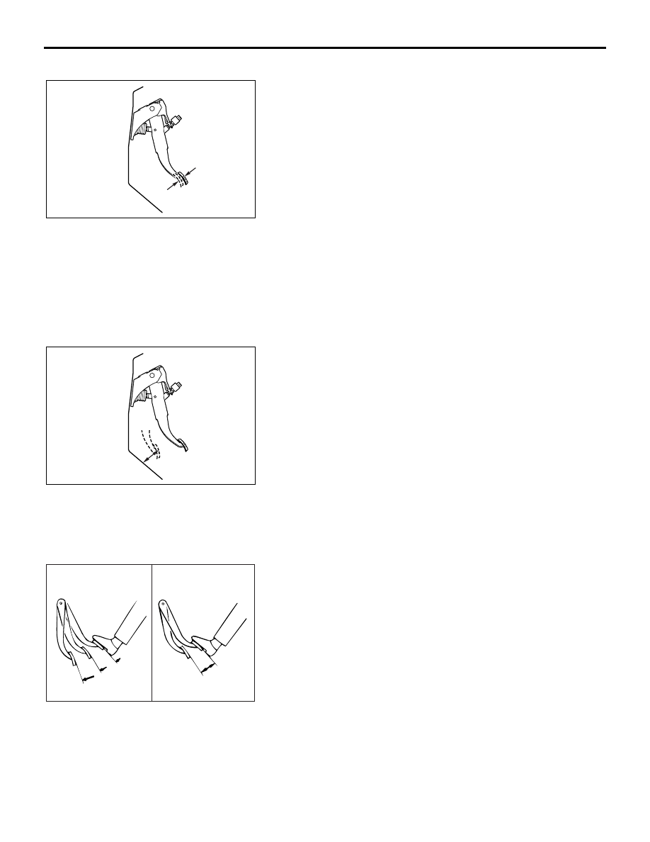
BRAKE BOOSTER OPERATING TEST

M1351001000372

1. For simple checking of the brake booster operation, carry 

out the following tests:

(1) Run the engine for one or two minutes, and then stop it. If 

the pedal depresses fully the first time but gradually 
becomes higher when depressed succeeding times, the 
booster is operating properly. If the pedal height remains 
unchanged, the booster is defective. Go to step 2.

AC206445

AB

AC206446

AB

AC000870

GOOD

NO GOOD

AB

ON-VEHICLE SERVICE

BASIC BRAKE SYSTEM

35A-15

(2) With the engine stopped, step on the brake pedal several 

times. Then step on the brake pedal and start the engine. 
If the pedal moves downward slightly, the booster is in 
good condition. If there is no change, the booster is 
defective. Go to step 3.

(3) With the engine running, step on the brake pedal and 

then stop the engine. Hold the pedal depressed for 30 
seconds. If the pedal height does not change, the booster 
is in good condition, if the pedal rises, the booster is 
defective.

2. If the above three tests are okay, the booster is OK. If one of 

the above three tests is not okay, the check valve, vacuum 
hose, or booster is defective. Check the check valve (Refer 
to 

P.35A-15

), vacuum hose for leaks, high volume engine 

vacuum applied to booster. Repair or replace as necessary. 
If these are OK, replace booster and repeat this test starting 
at Step 1.

CHECK VALVE OPERATION CHECK

M1351009000376

CAUTION

The check valve should not be removed from the vacuum 
hose.
1. Remove the vacuum hose. (Refer to 

P.35A-26

).

CAUTION

If the check valve is defective, replace it as an assembly 
together with the vacuum hose.
2. Check the operation of the check valve by using a vacuum 

pump.

AC000871AB

WHEN ENGINE

IS STOPPED

WHEN ENGINE

IS STARTED

AC000872

GOOD

NO GOOD

AB

VACUUM PUMP 
CONNECTION

CRITERIA

Connection at the brake 
booster side (A)

A negative pressure 
(vacuum) is created and 
held.

Connection at the intake 
manifold side (B)

A negative pressure 
(vacuum) is not created.

AC000873AB

A

B

VALVE

SPRING

INTAKE

MANIFOLD

SIDE

(DOES NOT

HOLD)

BOOST-

ER SIDE

(HOLDS)

ON-VEHICLE SERVICE

BASIC BRAKE SYSTEM

35A-16

BLEEDING

M1351001400455

CAUTION

Use only brake fluid DOT 3 or DOT 4. Never mix the speci-
fied brake fluid with other fluid as it will influence the brak-
ing performance significantly.

.

MASTER CYLINDER BLEEDING

The master cylinder used has no check valve, so if bleeding is 
carried out by the following procedure, bleeding of air from the 
brake pipeline will become easier. (When brake fluid is not con-
tained in the master cylinder).
1. Fill the reserve tank with brake fluid.

2. Keep the brake pedal depressed.
3. Have another person cover the master cylinder outlet with a 

finger.

4. With the outlet still closed, release the brake pedal.

5. Repeat steps 2 

− 4 three or four times to fill the inside of the 

master cylinder with brake fluid.

.

BRAKE LINE BLEEDING

Start the engine and bleed the air in the sequence shown in the 
figure.

15DB172A

OUTLET

15DB173A

4

2

1

3

VEHICLES WITH ABS

ON-VEHICLE SERVICE

BASIC BRAKE SYSTEM

35A-17

BRAKE FLUID LEVEL SENSOR CHECK

M1351009100403

The brake fluid level sensor is in good condition if there is no 
continuity when the float surface is above "MIN" and if there is 
continuity when the float surface is below "MIN".

DISC BRAKE PAD CHECK AND REPLACEMENT

M1351002300398

NOTE: Uneven wearor tapering of brake pad may be caused 
by either caliper piston not operating correctly  .

CAUTION

• Whenever a pad must be replaced, replace both LH and 

RH wheel pads as a set to prevent the vehicle from pull-
ing to one side when braking.

• If there is a significant difference in the thicknesses of 

the pads on the left and right sides, check the sliding 
condition of the piston and slide pins.

1. Check the brake pad thickness through the caliper body 

check port.(Rear). Front pad check can be viewed from rotor 
side.

Standard value: 10.0 mm (0.39 inch)
Minimum limit: 2.0 mm (0.08 inch)

15DB186A

15DB191A

WHEN NEW

WHEN WORN

PAD

BRAKE

DISC

15DB179A

<REAR>

15DB192A

<FRONT>


Content   ..  293  294  295  296   ..