Mitsubishi 380. Manual - part 292


  Index      Mitsubishi     Mitsubishi 380 - service repair manual 2005 year


Search            


Content   ..  290  291  292  293   ..


Mitsubishi 380. Manual - part 292


GENERAL DESCRIPTION

BASIC BRAKE SYSTEM

35A-2

GENERAL DESCRIPTION

M1351000100440

The brake system has been designed to give greater 
reliability and durability and to provide excellent brak-
ing performance.

FEATURES

.

Improved braking performance

1. An 8+9 inch tandem brake booster provides suffi-

cient braking force in sudden braking range.

2. 296mm front ventilated disc brakes provide sta-

ble braking force and improved braking feel. 

3. 303mm rear ventillated disc brakes are used.

.

Improved stability

1. A 4-wheel anti-lock braking system (4ABS) pre-

vents slipping caused by the vehicle wheels lock-
ing up, in order to maintain a stable vehicle 
posture and steering performance.

2. An electronic brake-force distribution (EBD) 

makes it possible to maintain the maximum 
amount of braking force even when the vehicle's 
load is unevenly distributed. 

3. Front- and rear-wheel X-type brake line layout 

are used.

4. Ventilated discs brakes improve anti-fading per-

formance.

.

Improved serviceability

1. A diagnosis function for the ABS system makes 

inspection easier.

2. An outer disc separated hub and rotor make 

removal and installation easier.

3. The master cylinder reservoir is utilised for both 

brake and clutch fluid on manual transmission 
vehicles.

4. The master cylinder filter is coloured black for 

improved viewing.

5. The ABS-ECU and hydraulic unit are integrated 

to make them more compact and light weight.

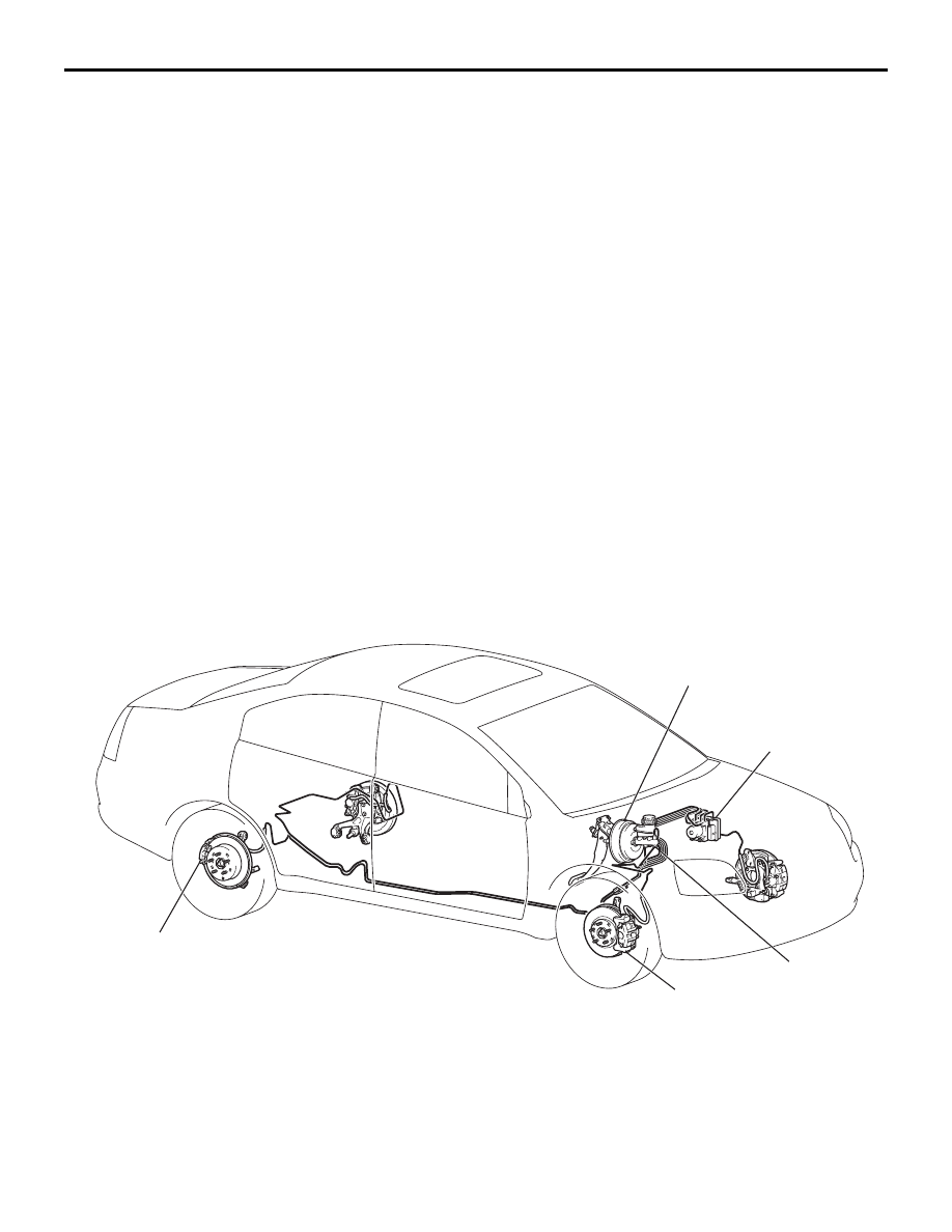
CONSTRUCTION DIAGRAM

BRAKE BOOSTER

HYDRAULIC UNIT

(INTEGRATED WITH

THE ABS-ECU)

MASTER CYLINDER

FRONT DISC BRAKE

REAR DISC BRAKE

<VEHICLE WITH ABS>

BASIC BRAKE SYSTEM DIAGNOSIS

BASIC BRAKE SYSTEM

35A-3

BASIC BRAKE SYSTEM DIAGNOSIS

INTRODUCTION TO BASIC BRAKE SYSTEM DIAGNOSIS

M1351009700319

Hydraulic brakes are composed of the brake pedal, 
master cylinder, brake booster and disc brakes. Mal-
functions such as insufficient braking power or the 
generation of noise may occur due to wear, damage 
or incorrect adjustment of these components.

BASIC BRAKE SYSTEM DIAGNOSTIC TROUBLESHOOTING STRATEGY

M1351009800316

Use these steps to plan your diagnostic strategy. If 
you follow them carefully, you will be sure that you 
have exhausted most of the possible ways to find a 
basic brake system fault.
1. Gather information from the customer.

2. Verify that the condition described by the 

customer exists.

3. Find the malfunction by following the symptom 

chart.

4. Verify malfunction is eliminated.

SYMPTOM CHART

M1351009900324

SYMPTOM PROCEDURES

INSPECTION PROCEDURE 1: Vehicle Pulls to One Side when Brakes are Applied

.

DIAGNOSIS

STEP 1. Check for oil, water, etc., on the pad 
contact surface of all brakes.

Q: Is oil, water, etc., on the pad contact surface?

YES : 

Replace the part and determine the 

source/cause of foreign material. Then go to 
Step 5.

NO : 

Go to Step 2.

SYMPTOM

INSPECTION 
PROCEDURE

REFERENCE 
PAGE

Vehicle pulls to one side when brakes are applied

1

P.35A-3

Insufficient braking power

2

P.35A-4

Increased pedal stroke (Reduced pedal-to-floor board clearance)

3

P.35A-5

Brake drag

4

P.35A-6

Scraping or grinding noise when brake are applied

5

P.35A-7

Squealing, groaning or chattering noise when brake are applied

6

P.35A-8

Squealing noise when brakes are not applied

7

P.35A-9

Groaning, clicking or rattling noise when brakes are not applied

8

P.35A-11

BASIC BRAKE SYSTEM DIAGNOSIS

BASIC BRAKE SYSTEM

35A-4

STEP 2. Check disc brake pistons for smooth 
operation.
(1) With engine not running, depress the brake pedal 

rapidly several times to deplete booster vacuum 
reserves.

(2) Test each disc brake assembly one at a time.

a. Remove the lower caliper bolt, then remove 

caliper from mount.

b. Have an assistant slowly depress the brake 

pedal. Confirm piston(s) extend slowly and 
smoothly with no jumpiness. Repeat for each 
disc brake assembly.

Q: Do (does) the piston(s) move correctly?

YES : 

Go to Step 3.

NO : 

Disassemble and inspect the brake 
assembly (Front: refer to 

P.35A-33

, Rear: 

refer to 

P.35A-36

). Then go to Step 5.

STEP 3. Check brake disc(s) for runout.
Refer to 

P.35A-19

.

Q: Is runout outside of specifications?

YES : 

Repair or replace the brake disc(s) as 

necessary. Then go to Step 5.

NO : 

Go to Step 4.

STEP 4. Check brake discs for correct thickness.
Refer to 

P.35A-19

.

Q: Is the thickness outside of specifications?

YES : 

Repair or replace the brake disc(s) as 

necessary. Then go to Step 5.

NO : 

Perform the brake line bleeding. Then go to 
Step 5.

STEP 5. Retest the system.

Q: Is the symptom eliminated?

YES : 

The procedure is complete.

NO : 

Start over at Step 1. If a new symptom 
appears, refer to the appropriate symptom 
chart.

INSPECTION PROCEDURE 2: Insufficient Braking Power

.

DIAGNOSIS

STEP 1. Check that the specified brake fluid is 
used, its level is correct, and no contamination is 
found.

Q: Is there a fault?

YES : 

Refill or replace with the specified brake 

fluid DOT 3 or DOT 4. Bleed the brakes if 
necessary (Refer to 

P.35A-16

). Then go to 

Step 7. 

NO : 

Go to Step 2. 

STEP 2. Check for spongy (not firm) brakes.
(1) With engine not running, depress the brake pedal 

rapidly several times to deplete the booster 
vacuum reserve.

(2) With the brake pedal fully released, depress the 

brake pedal slowly until it stops.

(3) With a measuring device (ruler, etc.) next to the 

brake pedal, depress the pedal firmly and 
measure the distance the pedal traveled.

Q: Is the distance greater than 20 mm (0.8 inch)?

YES : 

Bleed the brakes to remove air in the fluid 

(Refer to 

P.35A-16

). Then go to Step 7.

NO : 

Go to Step 3. 

STEP 3. Check the brake booster function.
Refer to 

P.35A-14

.

Q: Is there a fault?

YES : 

Replace the brake booster. Then go to Step 

7.

NO : 

Go to Step 4.

BASIC BRAKE SYSTEM DIAGNOSIS

BASIC BRAKE SYSTEM

35A-5

STEP 4. Check for pinched or restricted brake 
tube or hose.

Q: Is there a pinched or restricted brake tube or hose?

YES : 

Replace that complete section of brake tube 

or brake hose. Then go to Step 7.

NO : 

Go to Step 5.

STEP 5. Check for oil, water, etc., on the pad 
contact surfaces of all brakes.

Q: Is oil, water, etc., on the pad contact surface?

YES : 

Replace the part and determine the 

source/cause of foreign material. Recheck 
symptom. Then go to Step 7.

NO : 

The procedure is complete. If condition 
persists for vehicles without ABS, go to Step 
6.

STEP 7. Recheck symptom.

Q: Is the symptom eliminated?

YES : 

The procedure is complete.

NO : 

Start over at step 1. If a new symptom 
surfaces, refer to the appropriate symptom 
chart.

INSPECTION PROCEDURE 3: Increased Pedal Stroke (Reduced Pedal-to-Floor Board Clearance)

.

DIAGNOSIS

STEP 1. Check for spongy (not firm) brakes.
(1) With engine not running, depress the brake pedal 

rapidly several times to deplete booster vacuum 
reserve.

(2) With the brake pedal fully released, depress the 

brake pedal slowly until it stops.

(3) With a measuring device (ruler, etc.) next to the 

brake pedal, depress the pedal firmly and 
measure the distance the pedal traveled.

Q: Is the distance greater than 20 mm (0.8 inch)?

YES : 

Bleed the brakes to remove air in the fluid 

(Refer to 

P.35A-16

). Then go to Step 7.

NO : 

Go to Step 2.

STEP 2. Check the pad for wear.
Refer to 

P.35A-17

.

Q: Is the pad thickness outside of specifications?

YES : 

Replace the part. Then go to Step 7.

NO : 

Go to Step 3.

STEP 3. Check the vacuum hose and check valve 
for damage.
Refer to 

P.35A-15

.

Q: Is there a damage?

YES : 

Replace the part. Then go to Step 7.

NO : 

Go to Step 4.

STEP 4. Check the master cylinder function.
Refer to 

P.35A-23

.

Q: Is there a fault?

YES : 

Repair it. Then go to Step 7.

NO : 

Go to Step 5.

STEP 5. Check for brake fluid leaks.

Q: Is there a leak?

YES : 

Check the connection for looseness, 

corrosion, etc. Clean and repair as 
necessary. If leaking in any tube or hose 
section, replace the complete tube or hose. 
Then go to Step 7 .

NO : 

Go to Step 6.

STEP 6. Check for excessive clearance between 
the push rod and primary piston.
Refer to 

P.35A-26

.

Q: Is the clearance outside of specifications?

YES : 

Adjust the clearance. Then go to Step 7.

NO : 

Go to Step 7.

STEP 7. Recheck symptom.

Q: Is the symptom eliminated?

YES : 

The procedure is complete.

NO : 

Start over at step 1. If a new symptom 
surfaces, refer to the symptom chart.


Content   ..  290  291  292  293   ..