Mitsubishi Grandis. Manual - part 981
STEERING WHEEL
POWER STEERING
37-14
STEERING WHEEL
REMOVAL AND INSTALLATION
M1372011400309
WARNING
•
Before removing the steering wheel and air bag module assembly, refer to GROUP 52B,
Service Precautions (
) and Driver’s, Front Passenger’s Air Bag Module(s) and
Clock Spring (
).
•
When removing and installing the steering wheel, do not let it bump against the air bag
module.
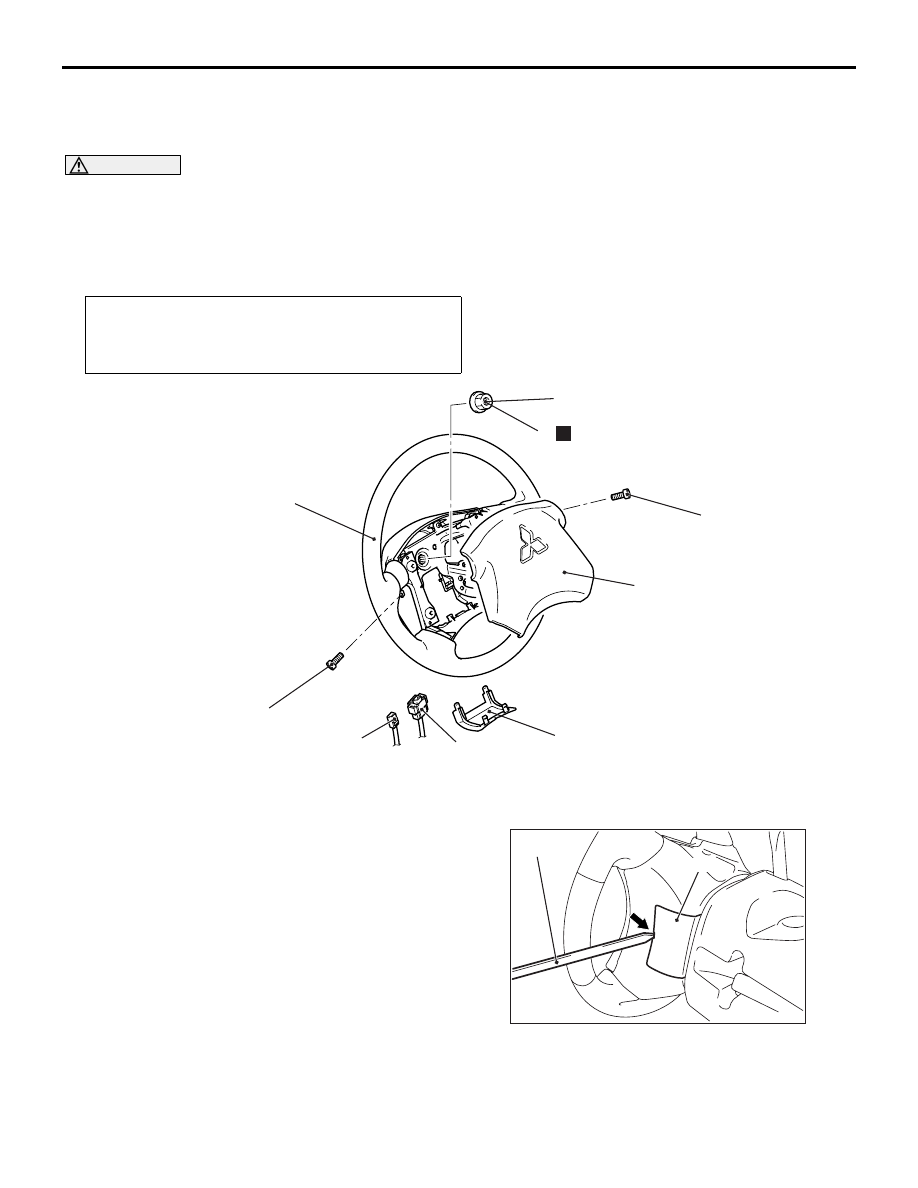
REMOVAL SERVICE POINTS
<<A>> COVER REMOVAL
Insert the special tool ornament remover
(MB990784) as shown in the illustration to remove
the cover.
Post-installation Operation
• Confirm that the steering wheel is at the straight-ahead
position.
• Steering wheel shake check
AC312094AB
41 ± 8 N·m
1
9.0 ± 2.0 N·m
N
2
3
4
5
6
9.0 ± 2.0 N·m
Removal steps
<<A>>
1. Cover
>>B<<
2. Horn connector connection
<<B>> >>B<<
3. Air bag module connector
connection
<<C>>
4. Air bag module
5. Self-locking nut
<<D>> >>A<<
6. Steering wheel assembly
AC302436AD
MB990784
Cover