Mitsubishi Grandis. Manual - part 980


  Index      Mitsubishi     Mitsubishi Grandis - service repair manual


Search            


Content   ..  978  979  980  981   ..


Mitsubishi Grandis. Manual - part 980


ON-VEHICLE SERVICE

POWER STEERING

37-10

TIE ROD END BALL JOINT TURNING 
TORQUE CHECK

M1372001500402

CAUTION

• Do not remove the tie rod end nut from the 

ball joint. Loosen it and use special tool to 
avoid possible damage to the ball joint 
threads.

• Hang special tool with cord to prevent it from 

falling. 

1. Install special tool ball joint remover (MB991897) 

as shown in the figure.

2. Turn the bolt and knob as necessary to make the 

jaws of special tool parallel, tighten the bolt by 
hand and confirm that the jaws are still parallel.
NOTE: When adjusting the jaws in parallel, make 
sure the knob is in the position shown in the 
figure.

3. Tighten the bolt with a wrench to disconnect the 

tie rod end.

4. Move the ball joint stud several times and install 

the nut on the stud. Using special tool preload 
socket (MB990326), measure the ball joint turning 
torque.

Standard value: 3.9 N

m or less

5. If the turning torque exceeds the standard value, 

replace the tie rod end. (Refer to 

P.37-24

)

6. If the turning torque is under the standard value, 

check the ball joint for axial play or ratcheting. If 
no axial play or ratcheting, the ball joint can be 
re-used. (Refer to 

P.37-24

)

CAUTION

Always use a new ball joint nut as it is a 
self-locking nut.
7. Install the tie rod end to the knuckle, then tighten a 

new self-locking nut to the specified torque.

Tightening torque: 25 

± 5 Nm

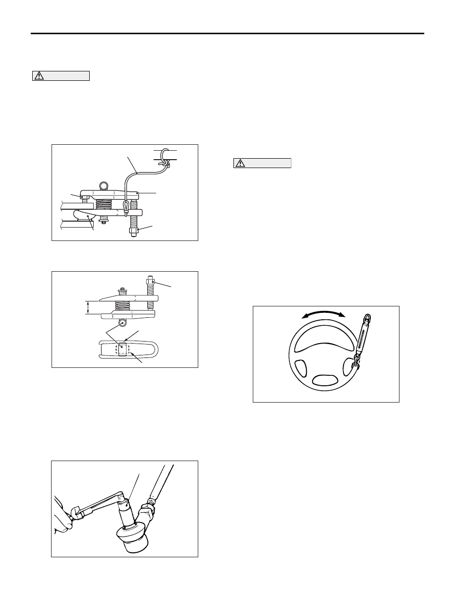
STATIONARY STEERING EFFORT CHECK

M1372001700451

1. With the vehicle stopped on a flat and paved 

surface, turn the steering wheel to the straight 
ahead position.

2. Start the engine and set the engine idle speed.

Standard value: 1000 

± 100 r/min

3. Attach a spring balance to the outer 

circumference of the steering wheel and measure 
the steering force required to turn the steering 
wheel from the straight ahead position to the left 
and right (within a range of 1.5 turns). Also check 
to be sure that there is no significant change in 
the required steering effort.

Standard value:

Steering effort: 25 N or less
Fluctuation allowance: 6.0 N or less

4. If the measured value exceeds the standard 

value, check and adjust the related parts.

AC208247AD

Cord

Bolt

MB991897

Nut

Ball joint

AC106821

Knob

Parallel

Bolt

Good

Bad

AB

ACX01129 AB

MB990326

ACX01122 AB

ON-VEHICLE SERVICE

POWER STEERING

37-11

STEERING WHEEL RETURN TO CENTRE 
CHECK

M1372001800403

Conduct a road test:
1. Make both gradual and sudden turns and check 

the steering wheel return. 

2. At a vehicle speed of approximately 35 km/h, turn 

the steering wheel 90

°, hold a few seconds, then 

release. If the steering wheel then returns 70

° or 

more, the return can be judged satisfactory.
NOTE: There will be a momentary feeling or 
"heaviness" when the wheel is turned quickly, but 
this is not abnormal (Oil pump discharge amount 
is especially apt to be insufficient during idling). 

DRIVE BELT TENSION CHECK

M1372001900369

Refer to GROUP 11A, On-vehicle Service 

− Drive 

Belt Tension Check 

P.11A-7

.

FLUID LEVEL CHECK

M1372002000381

1. Park the vehicle on a flat, level surface.
2. Start the engine, and then turn the steering wheel 

several times to raise the temperature of the fluid 
to approximately 50 

− 60°C.

3. With the engine running, turn the wheel all the 

way to the left and right several times.

4. Check the fluid in the oil reservoir for foaming or 

milkiness. Check the difference of the fluid level 
when the engine is stopped, and while it is 
running. If the change of the fluid level is 5 mm or 
more, air bleeding should be done.

FLUID REPLACEMENT

M1372002100441

1. Raise and support the front wheels.

2. Disconnect the return hose connection, and then 

connect a vinyl hose to the return hose, and drain 
the fluid into a container.

3. Disconnect the ignition coil connectors (Refer to 

GROUP 16, Ignition Coil 

P.16-27

).

4. While operating the starter motor intermittently, 

turn the steering wheel all the way to the left and 
right several times to drain all of the fluid.

5. Connect the return hose securely, and then 

secure with the clip.

6. Fill the oil reservoir with specified fluid up to 

between "MAX" and "MIN" marks, and then bleed 
the air.

Specified fluid: ATF DEXRON III or DEXRON 
II

POWER STEERING SYSTEM AIR 
BLEEDING

M1372002200437

Perform air bleeding procedure as necessary after 
replacing the steering gear or the steering fluid lines.
1. Raise and support the front wheels.
2. Disconnect the ignition coil connectors (Refer to 

GROUP 16, Ignition Coil 

P.16-27

).

ACX01130AB

70˚

70˚

ACX01131

While engine running

While engine stopped

AC

Fluid level change: Within 5 mm

AC313168AB

Return hose

Return hose

Vinyl hose

ON-VEHICLE SERVICE

POWER STEERING

37-12

CAUTION

Perform air bleeding only while cranking the 
engine. If air bleeding is performed while the 
engine is running, air could enter the fluid. 
During air bleeding, refill the steering fluid 
supply so that the level never falls below the 
"MIN" mark on the oil reservoir.
3. Turn the steering wheel all the way to the left and 

right five or six times while using the starter motor 
to crank the engine intermittently several times 
(for 15 to 20 seconds).

4. Connect the ignition coil connectors (Refer to 

GROUP 16, Ignition Coil 

P.16-27

).

5. Start the engine (idling).
6. Turn the steering wheel to the left and right until 

there are no air bubbles in the oil reservoir.

7. Confirm that the fluid is not milky, and that the 

level is between "MAX" and "MIN" marks.

8. Confirm that there is very little change in the fluid 

level when the steering wheel is turned left and 
right.

CAUTION

If the fluid level rises suddenly after the engine is 
stopped, the air has not been completely bled. If 
air bleeding is not complete, there will be 
abnormal noises from the pump and the 
flow-control valve, and this condition could 
cause reduce the life of the power steering 
components.

9. Confirm that the change in the fluid level is no 

more than 5 mm when the engine is stopped and 
when it is running.

10.If the change of the fluid level is 5 mm or more, 

the air has not been completely bled from the 
system. The air bleeding procedure must be 
repeated.

OIL PUMP PRESSURE TEST

M1372002300412

1. Disconnect the pressure hose from the oil pump, 

and then connect the following special tools.

• MB990662: Power Steering Oil Pressure Gauge

• MB991548: Power Steering Oil Pressure Gauge 

Adapter (pump side)

• MB991549: Power Steering Oil Pressure Gauge 

Adapter (hose side)

2. Bleed air, then turn the steering wheel several 

times while the vehicle is not moving so that the 
temperature of the fluid rises to approximately 50 
− 60°C.

3. Start the engine and idle it at 1000 

± 100 r/min.

4. Fully close the shut-off valve of the pressure 

gauge and measure the oil pump relief pressure 
to confirm that it is within the standard value 
range. Open it again immediately after checking 
the pressure.

Standard value: 9.8 

 10.3 MPa

5. If it is not within the standard value, replace the oil 

pump.

6. Check whether or not the hydraulic pressure is 

the standard value when no-load conditions are 
created by fully opening the shut-off valve of the 
pressure gauge.

Standard value: 0.2 

 0.7 MPa

ACX01131

While engine running

While engine stopped

AC

Fluid level change: Within 5 mm

ACX01133

Temperature
gauge

Oil reservoir

Adapter
(MB991548)

Oil 
pump

Adapter
(MB991549)

AB

Shut-off valve
(fully closed)

Pressure 
gauge
(MB990662)

ON-VEHICLE SERVICE

POWER STEERING

37-13

7. If it is not within the standard value, the probable 

cause is a malfunction of the oil line or steering 
gear, so check these parts and repair as 
necessary.

8. Turn the steering wheel all the way to the left or 

right; then check whether or not the retention 
hydraulic pressure is the standard value.

Standard value: 9.8 

 10.3 MPa

9. If not the standard value, overhaul the steering 

gear. Remeasure fluid pressure.

10. Remove the special tools, and then tighten the 

pressure hose to the specified torque.

Tightening torque: 57 

± 7 Nm

11. Bleed the system (Refer to 

P.37-11

).

TIE ROD END BALL JOINT DUST COVER 
CHECK

M1372008600358

1. Press the dust cover with your finger to check 

whether the dust cover is cracked or damaged.

2. If the dust cover is cracked or damaged, replace 

the tie rod end.
NOTE: If the dust cover is cracked or damaged, 
the ball joint could be damaged.

STEERING COLUMN SHAFT ASSEMBLY 
SHOCK ABSORBING MECHANISM 
CHECK

M1372013500250

If a collision accident occurs or severe impact is 
applied on the steering wheel, the collision energy 
absorbing mechanism may have operated. Once the 
mechanism has operated, it will be inoperative even 
it has suffered no apparent damage. Determine if the 
steering column shaft can be reused by the following 
procedure. If the collision energy absorbing 
mechanism has already operated, replace the 
steering column shaft assembly.
If any excessive radial free play on the steering 
wheel is found with the tilt lever in the lock position, 
always check the steering shaft assembly.

WARNING

If the vehicle continues to be driven after 
the collision absorbing mechanism has 
operated, the steering column shaft may 
be damaged while it is in use.

If there is a slack in the one-way capsule, 
do not attempt to repair it but replace the 
steering column shaft assembly.

Inspection Procedure

1. Remove the lower and upper column covers.

CAUTION

Do not release the tilt lever until the steering 
column has been installed to complete this 
inspection procedure.
2. Ensure that the tilt lever is in the lock position.

NOTE: If not, place the tilt lever in the lock 
position.

3. Loosen the two upper steering column mounting 

bolts by two turns.

4. Hold the one-way capsules as shown, and then 

try to lock them. If there is a slack in either of the 
capsules, replace the steering column shaft 
assembly.
NOTE: When installing a new steering column 
shaft assembly, place the tilt lever in the lock 
position, if it is not in place.

CAUTION

• Be careful that nothing is pinched between 

the one-way capsules and the body.

• Do not release the tilt lever until the steering 

column has been installed to complete this 
inspection procedure.

5. If no problem is found during the inspection, 

tighten the steering column mounting bolts to the 
specified torque.

Tightening torque: 12 

± 2 Nm

AC209935

Steering
column 
assembly

AC

One way capsule

Steering
column 
mounting 
bolt


Content   ..  978  979  980  981   ..