Mitsubishi Grandis. Manual - part 953


  Index      Mitsubishi     Mitsubishi Grandis - service repair manual


Search            


Content   ..  951  952  953  954   ..


Mitsubishi Grandis. Manual - part 953


TROUBLESHOOTING

TRACTION CONTROL/ACTIVE STABILITY CONTROL SYSTEM

35C-137

DIAGNOSIS

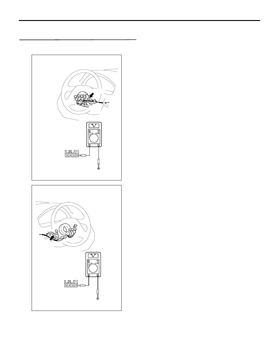
STEP 1. Voltage measurement at steering wheel 
sensor connector C-306.

(1) Disconnect the connector C-306.

(2) Turn the ignition switch to the "ON" position.
(3) Measure the voltage between terminal 2 and 

earth.

OK: System voltage

Q: Is the check result normal?

YES : 

Go to Step 3.

NO : 

Go to Step 2.

AC313221

C-306

Connector: C-306
<L.H.drive vehicles>

C-306 Harness
connector
(harness side)

AB

AC313222

C-306

Connector: C-306
<R.H.drive vehicles>

C-306 Harness
connector
(harness side)

AB

TROUBLESHOOTING

TRACTION CONTROL/ACTIVE STABILITY CONTROL SYSTEM

35C-138

STEP 2. Check the following connectors.

Junction block connectors C-202 and C-203

Joint connector C-01 <LH drive vehicles> or C-33 

<RH drive vehicles> and intermediate connector 
C-124

AC313139

AB

C-203

Connectors: C-202, C-203
<L.H.drive vehicles>

C-202

C-202

C-203

1

3 4

2

6

5

6

1

7

2

9

8

10

3

5

12

11

4

1314

Junction block
(Front view)

AC313140

AB

C-203

Connectors: C-202, C-203
<R.H.drive vehicles>

C-202

C-202

C-203

1

3 4

2

6

5

6

1

7

2

9

8

10

3

5

12

11

4

1314

Junction block
(Front view)

AC211226

33

22

11

28

17

16

15

14

13

12

25

2324

2627

3

1 2

4 5

21

20

19

18
2930

32

31

7

6

8

10

9

AC

CONNECTOR: C-04

C-04

AC312624

33

22

11

28

17

16

15

14

13

12

25

2324

2627

3

1 2

4 5

21

20

19

18
2930

32

31

7

6

8

10

9

AC

Connectors: C-01, C-124
<L.H.drive vehicles>

C-01

C-01

C-124

C-124

AC312625AC

Connectors: C-33, C-124
<R.H.drive vehicles>

C-33

C-33

C-124

C-124

TROUBLESHOOTING

TRACTION CONTROL/ACTIVE STABILITY CONTROL SYSTEM

35C-139

Ignition switch connector C-307

Steering wheel sensor connector C-306
Check the connectors, for loose, corroded or 
damaged terminals, or terminals pushed back in the 
connector.

Q: Is the check result normal?

YES : 

An open or short circuit may be present in 

the power supply line to the steering wheel 
sensor. Repair the wiring harness between 
steering wheel sensor connector C-306 
terminal 2 and ignition switch connector 
C-307 terminal 2. Go to Step 8.

NO : 

Repair or replace the damaged 
component(s). Refer to GROUP 00, How to 
Use Troubleshooting/Inspection Service 
Points 

− How to Cope with Intermittent 

Malfunction 

P.00-5

. Then go to Step 8.

AC313147AB

Connector: C-307
<L.H.drive vehicles>

C-307

2
5

4

1

6

3

AC313148

AB

Connector: C-307
<R.H.drive vehicles>

C-307

2
5

4

1

6

3

AC313147

C-306

Connector: C-306
<L.H.drive vehicles>

AC

AC313148

C-306

Connector: C-306
<R.H.drive vehicles>

AC

TROUBLESHOOTING

TRACTION CONTROL/ACTIVE STABILITY CONTROL SYSTEM

35C-140

STEP 3. Resistance measurement at steering 
wheel sensor connector C-306.

(1) Disconnect the steering sensor connector C-306, 

and measure at the harness side connector.

(2) Measure the resistance between terminal 5 and 

body earth. 

OK: 2 ohm or less

Q: Is the check result normal?

YES : 

Go to Step 5.

NO : 

Go to Step 4.

STEP 4. Check steering wheel sensor connector 
C-306 for loose, corroded or damaged terminals, 
or terminals pushed back in the connector.

Q: Is the check result normal?

YES : 

An open circuit may be present in the earth 

circuit. Repair the wiring harness between 
steering wheel sensor connector C-306 
terminals 5 and the body earth. Then go to 
Step 8.

NO : 

Repair or replace the damaged 
component(s). Refer to GROUP 00, How to 
Use Troubleshooting/Inspection Service 
Points 

− How to Cope with Intermittent 

Malfunction 

P.00-5

. Then go to Step 8.

STEP 5. Check the battery.

Check the battery (Refer to GROUP 54A, Battery 
test 

P.54A-6

).

Q: Is the check result normal?

YES : 

Go to Step 6.

NO : 

Charge or replace the battery. Then go to 
Step 8.

STEP 6. Check the charging system.

Check the charging system (Refer to GROUP 16, 
Charging system diagnosis 

P.16-5

).

Q: Is the check result normal?

AC313221

C-306

Connector: C-306
<L.H.drive vehicles>

C-306 Harness
connector
(harness side)

AC

AC313222

C-306

Connector: C-306
<R.H.drive vehicles>

AC

C-306 Harness
connector
(harness side)

AC313147

C-306

Connector: C-306
<L.H.drive vehicles>

AC

AC313148

C-306

Connector: C-306
<R.H.drive vehicles>

AC


Content   ..  951  952  953  954   ..