Mitsubishi Grandis. Manual - part 952


  Index      Mitsubishi     Mitsubishi Grandis - service repair manual


Search            


Content   ..  950  951  952  953   ..


Mitsubishi Grandis. Manual - part 952


TROUBLESHOOTING

TRACTION CONTROL/ACTIVE STABILITY CONTROL SYSTEM

35C-133

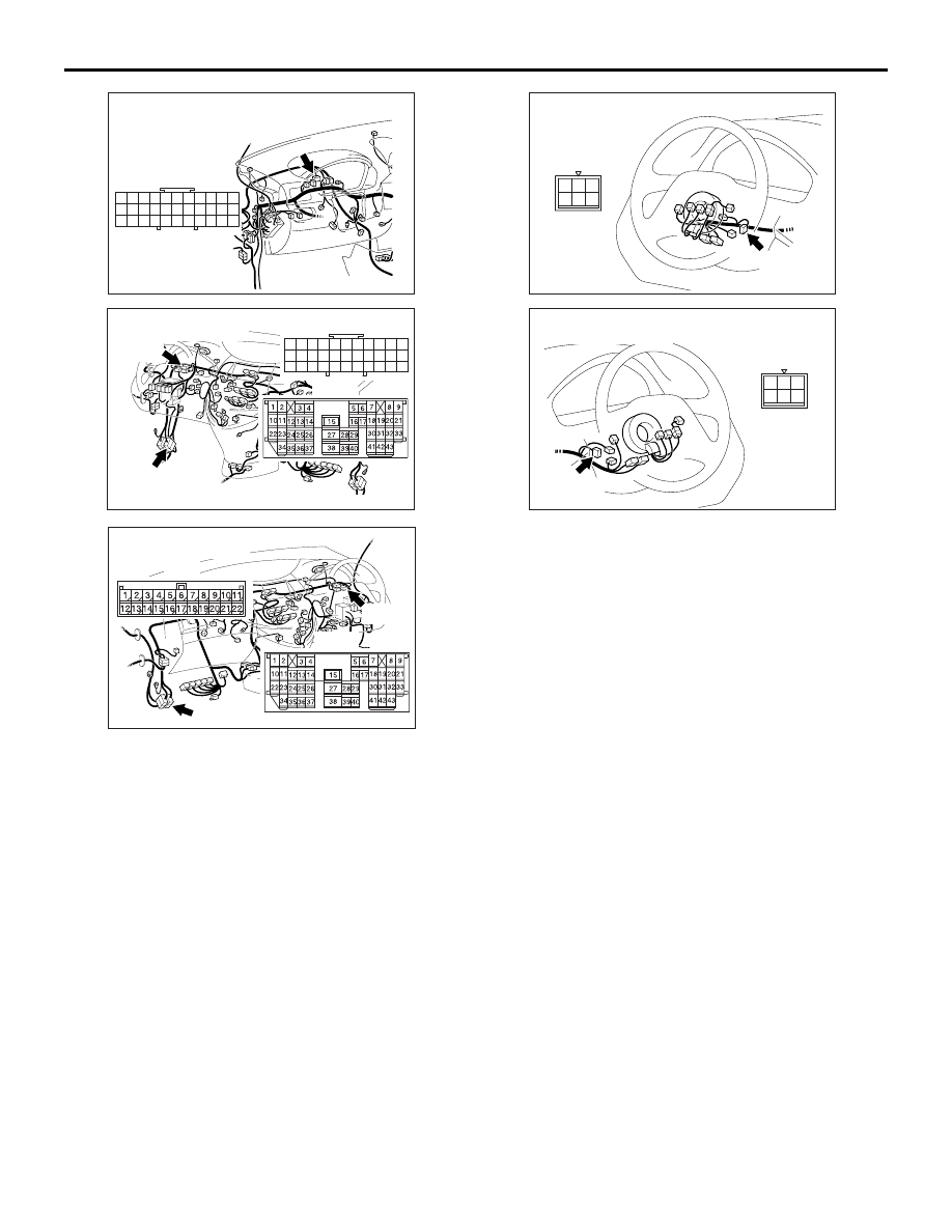
Joint connector C-01 <LH drive vehicles> or C-33 

<RH drive vehicles> and intermediate connector 
C-124

Ignition switch connector C-307
Check the connectors, for loose, corroded or 
damaged terminals, or terminals pushed back in the 
connector.

Q: Is the check result normal?

YES : 

An open or short circuit may be present in 

the power supply line to the TCL/ASC-ECU. 
Repair the wiring harness between 
TCL/ASC-ECU connector A-04 terminal 4 
and ignition switch connector C-307 
terminal 2. Go to Step 8.

NO : 

Repair or replace the damaged 
component(s). Then go to Step 8.

AC211226

33

22

11

28

17

16

15

14

13

12

25

2324

2627

3

1 2

4 5

21

20

19

18
2930

32

31

7

6

8

10

9

AC

CONNECTOR: C-04

C-04

AC312624

33

22

11

28

17

16

15

14

13

12

25

2324

2627

3

1 2

4 5

21

20

19

18
2930

32

31

7

6

8

10

9

AC

Connectors: C-01, C-124
<L.H.drive vehicles>

C-01

C-01

C-124

C-124

AC312625AC

Connectors: C-33, C-124
<R.H.drive vehicles>

C-33

C-33

C-124

C-124

AC313147AB

Connector: C-307
<L.H.drive vehicles>

C-307

2
5

4

1

6

3

AC313148

AB

Connector: C-307
<R.H.drive vehicles>

C-307

2
5

4

1

6

3

TROUBLESHOOTING

TRACTION CONTROL/ACTIVE STABILITY CONTROL SYSTEM

35C-134

STEP 3. Resistance measurement at 
TCL/ASC-ECU connector A-04.

(1) Disconnect the connector A-04, and connect 

special tool ABS Check Harness (MB991997) to 
the wiring harness-side connector.
NOTE: Do not connect special tool ABS Check 
Harness (MB991997) to the TCL/ASC-ECU.

(2) Measure the resistance between terminal 16 and 

earth.

OK: 2 ohm or less

Q: Is the check result normal?

YES : 

Go to Step 5.

NO : 

Go to Step 4.

STEP 4. Check TCL/ASC-ECU connector A-04 for 
loose, corroded or damaged terminals, or 
terminals pushed back in the connector.

Q: Is the check result normal?

YES : 

An open circuit may be present in the earth 

circuit. Repair the wiring harness between 
TCL/ASC-ECU connector A-04 terminals 16 
and the body earth. Then go to Step 8.

NO : 

Repair or replace the damaged 
component(s). Then go to Step 8.

STEP 5. Check the battery.

Check the battery (Refer to GROUP 54A, Battery 
test 

P.54A-6

).

Q: Is the check result normal?

YES : 

Go to Step 6.

NO : 

Charge or replace the battery. Then go to 
Step 8.

STEP 6. Check the charging system.

Check the charging system (Refer to GROUP 16, 
Charging system 

P.16-5

).

Q: Is the check result normal?

YES : 

Go to Step 7.

NO : 

Repair or replace the charging system 
component(s).Then go to Step 8.

AC312620AF

Oil reservoir

Connector: A-04

TCL/ASC-ECU

MB991997

Check connector

A-04 Harness connector

A-04

Hydraulic unit
(with built-in TCL/ASC-ECU)

AC312621

Oil reservoir

Connector: A-04

AB

A-04

Hydraulic unit
(with built-in TCL/ASC-ECU)

A-04 Harness connector
(harness side)

TROUBLESHOOTING

TRACTION CONTROL/ACTIVE STABILITY CONTROL SYSTEM

35C-135

STEP 7. Retest the system.

Q: Can the TCL/ASC-ECU communicate with the 

MUT-III?

YES : 

It can be assumed that this malfunction is 

intermittent. Refer to GROUP 00, How to 
Use Troubleshooting/Inspection Service 
Points 

− How to Cope with Intermittent 

Malfunction 

P.00-5

.

NO : 

Replace the TCL/ASC-ECU. Then go to 
Step 8.

STEP 8. Retest the system.

Q: Can the TCL/ASC-ECU communicate with the 

MUT-III?

YES : 

The procedure is complete.

NO : 

Go to Step 1.

INSPECTION PROCEDURE 4: Steering wheel sensor power supply supply system

<LH drive vehicles>

IGNITION 
SWITCH (IG1)

STEERING
WHEEL
SENSOR

Wire colour code
B : Black 
LG : Light green
G : Green
L: Blue 
W : White
Y: Yellow
SB : Sky blue
BR : Brown
O : Orange
GR : Gray
R : Red
P : Pink
V : Violet

Steering Wheel Sensor Power Supply Circuit

TROUBLESHOOTING

TRACTION CONTROL/ACTIVE STABILITY CONTROL SYSTEM

35C-136

<RH drive vehicles>

OPERATION

• The steering wheel sensor is energized by the 

ignition switch (IG1) through multi-purpose fuse 2 
and the steering wheel sensor terminal 2.

• If the power supply to the steering wheel sensor 

has failed, MUT-III will not be able to 
communicate with it.

PROBABLE CAUSES

• Damaged wiring harness or connector

• Defective battery

• Charging system failed

• Malfunction of the steering wheel sensor

IGNITION 
SWITCH (IG1)

STEERING
WHEEL
SENSOR

Wire colour code
B : Black 
LG : Light green
G : Green
L: Blue 
W : White
Y: Yellow
SB : Sky blue
BR : Brown
O : Orange
GR : Gray
R : Red
P : Pink
V : Violet

Steering Wheel Sensor Power Supply Circuit


Content   ..  950  951  952  953   ..