Mitsubishi Grandis. Manual - part 894
FRONT DISC BRAKE ASSEMBLY
BASIC BRAKE SYSTEM
35A-18
DISASSEMBLY SERVICE POINT
<<A>> CIRCLIP REMOVAL
While pushing the primary piston assembly, remove
the circlip.
INSPECTION
M1351004300349
• Check the inner surface of master cylinder body
for rust or pitting.
• Check the primary and secondary pistons for
rust, scoring, wear or damage.
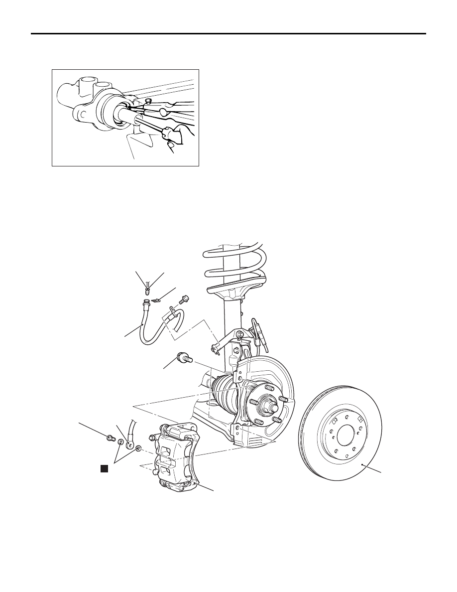
FRONT DISC BRAKE ASSEMBLY
REMOVAL AND INSTALLATION
M1351006000537
AC104263
AC311384 AB
100 ± 10 N·m
30 ± 4 N·m
3
1
2
N
6
7
5
15 ± 2 N·m
4
Removal steps
•
Brake fluid draining
1. Brake hose connection
2. Gasket
3. Front brake assembly
<<A>>
4. Front brake disc
5. Clip
6. Brake pipe and brake hose
connection
7. Brake hose
Removal steps (Continued)