Mitsubishi Grandis. Manual - part 892
ON-VEHICLE SERVICE
BASIC BRAKE SYSTEM
35A-10
CAUTION
• After a new brake disc is installed, always
grind the brake disc with on-the-car type
brake lathe. If this step is not carried out, the
brake disc run-out exceeds the specified
value, resulting in judder.
•
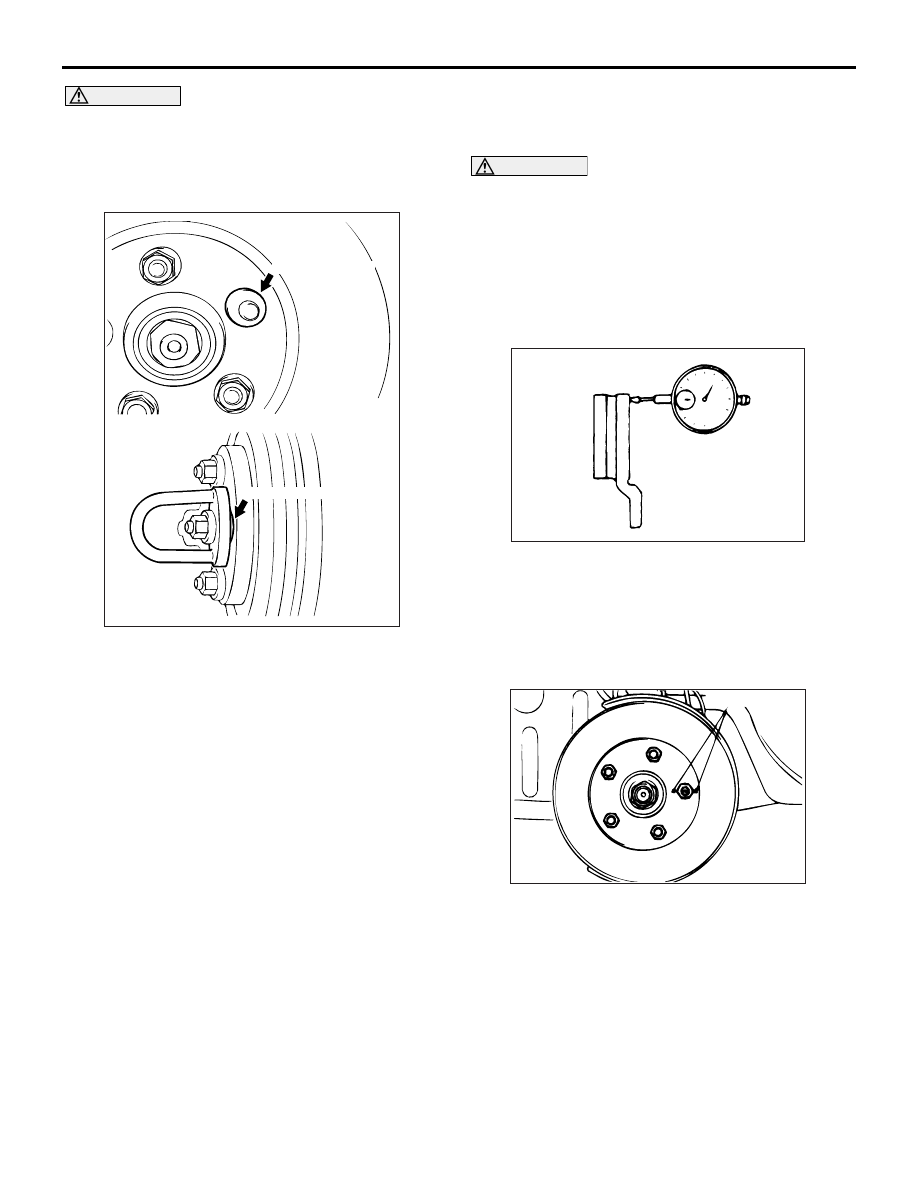
When the on-the-car type lathe is used, first
install M12 flat washer on the stud bolt in the
brake disc side according to the figure, and
then install the adapter. If the adapter is
installed with M12 flat washer not seated, the
brake disc rotor may be deformed, resulting
in inaccurate grinding.
• Grind the brake disc with all wheel nuts
diagonally and equally tightened to the
specified torque 100 N
⋅m. When all numbers
of wheel nuts are not used, or the tightening
torque is excessive or not equal, the brake
disc rotor or drum may be deformed,
resulting in judder.
2. If the disc thickness is less than the limits, replace
it with a new one. If thickness variation exceeds
the specification, turn rotor with an on-the-car type
brake lathe ("MAD, DL-8700PF" or equivalent). If
the calculated final thickness after turning the
rotor is less than the standard value, replace the
disc.
BRAKE DISC RUN-OUT CHECK AND
CORRECTION
CAUTION
The vehicle speed detection magnetic encoder
collects any metallic particle easily, because it is
magnetised. When replacing brake disc, make
sure that the magnetic encoder does not collect
any metallic particle.
1. Remove the brake caliper assembly, and then
hold it with wire.
2. Temporarily install the disc with the hub nut.
3. Place a dial gauge approximately 5 mm from the
outer circumference of the brake disc, and
measure the run-out of the disc.
Limit:
<Front> 0.03 mm
<Rear> 0.04 mm
4. If the brake disc run-out exceeds the limit, correct
it as follows:
(1) Chalk phase marks on the wheel stud and the
brake disc, which run-out is excessive as
shown.
AC006226AD
M12 Flat washer
M12 Flat washer
ACX00669
AC201323AC
Chalk marks