Mitsubishi Grandis. Manual - part 890


  Index      Mitsubishi     Mitsubishi Grandis - service repair manual


Search            


Content   ..  888  889  890  891   ..


Mitsubishi Grandis. Manual - part 890


GENERAL INFORMATION

BASIC BRAKE SYSTEM

35A-2

GENERAL INFORMATION

M1351000100547

The brake system has been designed to give greater 
reliability and durability and to provide excellent 
braking performance.

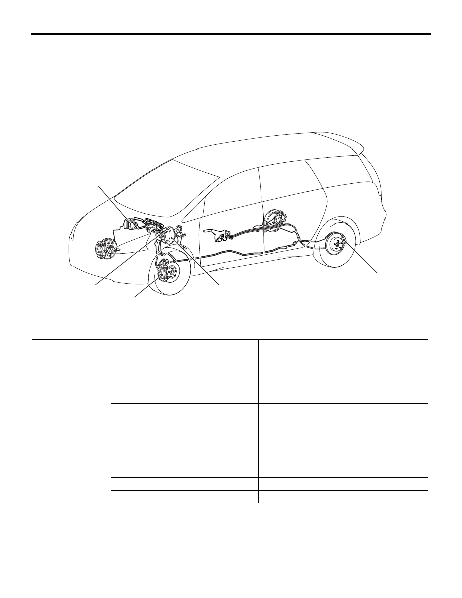
CONFIGURATION DIAGRAM

SPECIFICATIONS

AC312153

Brake booster

Rear disc brake

Master cylinder

Front disc brake

Hydraulic unit

AC

Item

Specification

Master cylinder

Type

Tandem type

I.D. mm

25.4

Brake booster

Type

Vacuum type, tandem

Effective dia. of power cylinder mm

205 + 230

Boosting ratio

8.5 (pedal pressure: 60 N)
10.5 (pedal pressure: 110 N)

Rear wheel hydraulic control method

Electronic brake-force distribution (EBD)

Front brakes

Type

Floating caliper, 2 piston, ventilated disc

Disc effective dia. 

× thickness mm

241 

× 26

Wheel cylinder I.D. mm

45.4 

× 2

Pad thickness mm

10.0

Clearance adjustment

Automatic

SERVICE SPECIFICATIONS

BASIC BRAKE SYSTEM

35A-3

SERVICE SPECIFICATIONS

M1351000300585

LUBRICANTS

M1351000400515

Rear disc brakes

Type

Floating caliper, 1 piston, solid disc

Disc effective dia. 

× thickness mm

258 

× 10

Wheel cylinder I.D. mm

38.1

Pad thickness mm

10.0

Clearance adjustment

Automatic

Brake fluid

DOT3 or DOT4

Item

Specification

Item

Standard value

Limit

Brake pedal height mm

211 

− 214

Brake pedal free play mm

− 8

Brake pedal to floor board clearance mm

140 or more

Disc brake pad thickness mm

10.0

2.0

Disc brake disc thickness mm

Front

26.0

24.4

Rear

10.0

8.4

Disc brake disc run-out mm

Front

0.03

Rear

0.04

Disc brake drag force N

Front/Rear

68 or less

Wheel bearing axial play mm

Front/Rear

0.05

Brake booster push rod protruding length mm (When applying 
negative pressure of 66.7 kPa to the brake booster)

11.3 

− 11.7

Item

Specified lubricant

Quantity

Brake fluid

DOT3 or DOT4

As required

Primary piston assembly, secondary piston 
assembly, master cylinder body, caliper body, piston, 
piston seal
Guide pin, lock pin, bushing, pin boot, piston boot, 
boot ring

Repair kit grease

As required

SPECIAL TOOLS

BASIC BRAKE SYSTEM

35A-4

SPECIAL TOOLS

M1351000600445

ON-VEHICLE SERVICE

BRAKE PEDAL CHECK AND 
ADJUSTMENT

M1351000900521

BRAKE PEDAL HEIGHT

1. Turn up the carpet, etc. under the brake pedal.

2. Measure the brake pedal height as illustrated.

Standard value (A): 211 

 214 mm 

[From the surface of dash panel to the face 
of pedal pad]

3. If the brake pedal height is not within the standard 

value, follow the procedure below.
(1) Disconnect the stop lamp switch connector.
(2) Loosen the stop lamp switch by turning it 

approximately one quarter of a turn 
anticlockwise. 

(3) Remove the brake pedal assembly (Refer to 

P.35A-12

).

(4) Adjust the brake pedal height by turning the 

clevis of brake booster.

NOTE: When the clevis is turned 180

°

, the 

pedal height is changed approximately 2 mm.

(5) Install the brake pedal assembly (Refer to 

P.35A-12

).

(6) Screw in the stop lamp switch until its thread 

contacts the stopper, and fix the stop lamp 
switch by turning it approximately one quarter 
of a turn clockwise.

Tool

Number

Name

Use

MB991568

Push rod adjusting 
socket

Adjustment of the brake booster 
push rod protrusion amount

MB990964
A: MB990520

Brake tool set
A: Disc brake 
piston expander

Pushing-in of the disc brake 
piston

MB990964

A

B

AC301990 AE

A

Stop lamp
switch

AC303157AC

Pin

Brake pedal assembly

Stop lamp
switch

Clevis

Brake booster

ON-VEHICLE SERVICE

BASIC BRAKE SYSTEM

35A-5

(7) Measure the brake pedal height, and ensure 

that the measured value is within the standard 
value. When it is out of the standard value, 
repeat Step (3) - (6).

(8) Check that the clearance between the stop 

lamp switch and the stopper is as shown.

CAUTION

Check that the stop lamp does not illuminate 
when the brake pedal is not depressed.

(9) Connect the connector at the stop lamp 

switch.

4. For vehicles with A/T, check the key interlock/shift 

lock mechanism (Refer to GROUP 23A, 
On-vehicle service 

− key interlock/shift lock 

mechanism check and adjustment

P.23A-139

).

5. Return the carpet, etc.

BRAKE PEDAL FREE PLAY

1. Turn the ignition switch to the "LOCK" (OFF) 

position, depress the brake pedal two or three 
times. After eliminating the vacuum in the brake 
booster, press the pedal down by hand, and 
confirm that the amount of movement before 
resistance is met (free play) is within the standard 
value range.

Standard value: 3 

 8 mm

2. If the brake pedal play is not within the standard 

value, check the following, and adjust or replace if 
necessary:

• Excessive play between the brake pedal and the 

clevis pin, or between the clevis pin and the 
brake booster operating rod

• Brake pedal height

• Installation position of the stop lamp switch, etc.

CLEARANCE BETWEEN BRAKE PEDAL 
AND FLOOR BOARD

1. Turn up the carpet, etc. under the brake pedal.

2. Start the engine, depress the brake pedal with 

approximately 500 N of force, and measure the 
clearance between the brake pedal and the floor 
board.

Standard value (C): 140 mm or more
[From the surface of floor board to the face 
of pedal pad]

3. If the clearance is outside the standard value, 

check for air trapped in the brake line, thickness of 
the disc brake pad, clearance between the lining 
and the drum and dragging in the parking brake. 
And then adjust and replace defective parts as 
required.

4. Return the carpet etc. to its original position.

BRAKE BOOSTER OPERATING TEST

M1351001000446

1. For simple checking of the brake booster 

operation, carry out the following tests:

AC313310AB

0.5 – 1.5 mm

Stop lamp switch

Pedal stopper

AC301990AF

B

AC301990AG

C

AC000870

Good

No good

AE


Content   ..  888  889  890  891   ..