Mitsubishi Grandis. Manual - part 893
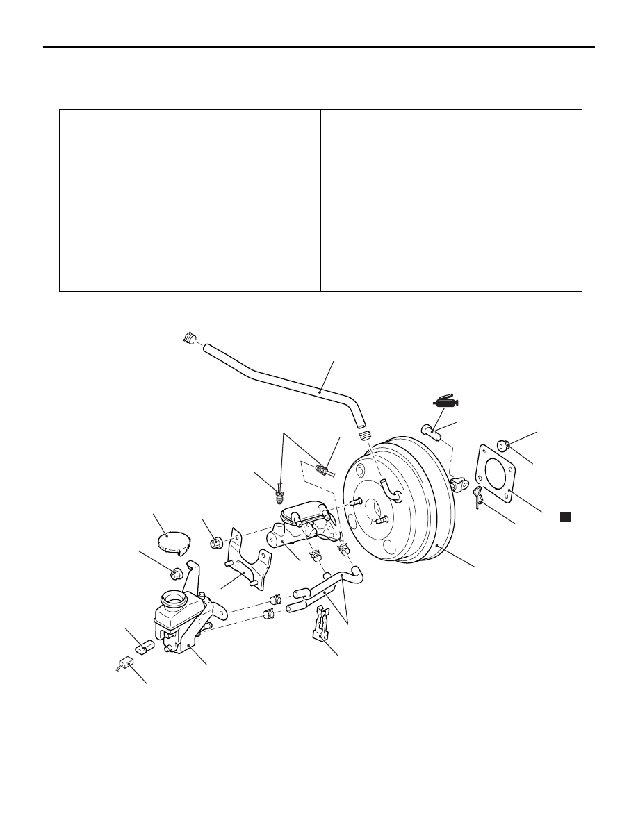
MASTER CYLINDER ASSEMBLY AND BRAKE BOOSTER
BASIC BRAKE SYSTEM
35A-14
MASTER CYLINDER ASSEMBLY AND BRAKE BOOSTER
REMOVAL AND INSTALLATION
M1351003700548
<LH drive vehicles>
Pre-removal Operation
• Air Cleaner Resonator, Air Cleaner Cover, Air Cleaner
Intake Duct, Air Cleaner Body Assembly Removal (Refer
to GROUP 15, Air Cleaner
.) <LH drive vehicles>
• Engine Cover and Engine Cover Bracket Removal (Refer
to GROUP 11A, Camshaft and Valve Stem Seal
.) <LH drive vehicles>
• Air Intake Hose Removal (Refer to GROUP 15, Air
Cleaner
.) <LH drive vehicles>
• Canister removal (Refer to GROUP 17, Evaporative
Emission Control System
− Canister
.) <LH drive
vehicles>
• Brake Fluid Draining
Post-installation Operation
• Brake Fluid Supplying and Air Bleeding (Refer to
.)
• Canister Installation (Refer to GROUP 17, Evaporative
Emission Control System
− Canister
.) <LH drive
vehicles>
• Brake Pedal Adjustment (Refer to
• Air Intake Hose Installation (Refer to GROUP 15, Air
Cleaner
.) <LH drive vehicles>
• Engine Cover and Engine Cover Bracket Installation
(Refer to GROUP 11A, Camshaft and Valve Stem Seal
.) <LH drive vehicles>
• Air Cleaner Resonator, Air Cleaner Cover, Air Cleaner
Intake Duct, Air Cleaner Body Assembly Installation
(Refer to GROUP 15, Air Cleaner
vehicles>
AC312193
AB
1
10
12
14
13
15 ± 2 N·m
14 ± 3 N·m
6
11
15
N
8
14.7 ± 2.9 N·m
2
7
5
3
4
13 ± 2 N·m
9
7
Master cylinder removal steps
1.
Brake fluid level switch connector
2.
Hose clip
>>C<<
3.
Reservoir hose
4.
Reservoir assembly
5.
Reservoir cap
6.
Brake fluid level switch
7.
Brake pipe connection
•
Brake pipe [between brake master
cylinder and hydraulic unit
(ABS-ECU)] (Refer to GROUP 35B,
Hydraulic Unit
Master cylinder removal steps