Mitsubishi Grandis. Manual - part 876
TRANSMISSION
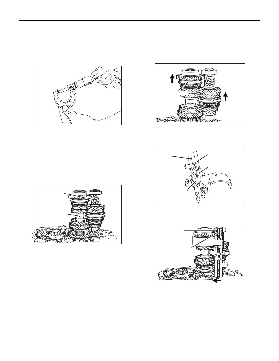
MANUAL TRANSMISSION OVERHAUL
22B-14
3. Install the clutch housing and tighten the bolts to
the specified torque of 44
± 5 N⋅m.
4. Remove the clutch housing, and then remove the
differential assembly.
5. Remove the outer race and take out crushed
solders.
6. Measure the thickness of the crushed solder with
a micrometer and select a spacer that will provide
the standard preload value.
Standard value: 0.05
− 0.11 mm preload
REASSEMBLY SERVICE POINTS
>>A<< OUTPUT SHAFT/INPUT SHAFT
INSTALLATION
Install the input and output shafts together.
>>B<< 5TH SPEED-REVERSE SHIFT
FORK/5TH SPEED-REVERSE SHIFT
RAIL/3RD-4TH SPEED SHIFT
FORK/3RD-4TH SPEED SHIFT RAIL
INSTALLATION
1. Shift the 3rd-4th speed synchronizer sleeve and
5th speed-reverse synchronizer sleeve in the
direction shown.
2. Assemble the 3rd-4th speed shift rail and fork,
and the 5th speed-reverse shift rail and fork.
3. While fitting each shift fork in the groove of
synchronizer sleeve, slide the shift rails in the
direction shown and install.
4. Insert the 3rd-4th speed shift rail and 5th
speed-reverse shift rail into the rail hole in the
clutch housing.
>>C<< SPRING PIN INSTALLATION
1. Align the pin holes in the shift rail and shift fork.
AK305233
AK305106AB
Input shaft
Output shaft
AK305111AB
3rd-4th speed
synchronizer
sleeve
5th speed-reverse
synchronizer
sleeve
AK305112AB
3rd-4th speed
shift rail
3rd-4th speed
shift fork
5th speed-reverse
shift fork
5th speed-reverse
shift rail
AK305104AC
3rd-4th speed
shift rail
5th speed-reverse
shift rail