Mitsubishi Grandis. Manual - part 872


  Index      Mitsubishi     Mitsubishi Grandis - service repair manual


Search            


Content   ..  870  871  872  873   ..


Mitsubishi Grandis. Manual - part 872


CLUTCH

CLUTCH OVERHAUL

21B-4

REMOVAL SERVICE POINT
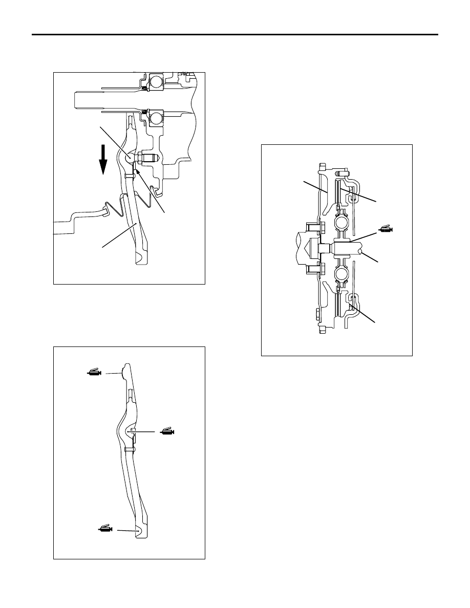
<<A>> RELEASE FORK REMOVAL

Move the release fork in the direction shown to 
remove the clip from the fulcrum.

INSTALLATION SERVICE POINTS
>>A<< RELEASE FORK INSTALLATION

1. Apply grease to the illustrated positions of the 

release fork.

Specified grease:

Mitsubishi genuine grease Part No.0101011 or 

equivalent

2. Install the release fork to the fulcrum.

>>B<< CLUTCH DISC AND CLUTCH 
COVER INSTALLATION

1. Apply grease to the clutch disc splines and rub it 

in the splines with a brush.

Specified grease:

Mitsubishi genuine grease Part No.0101011 or 

equivalent

2. Using the clutch disc guide to position the clutch 

disc on the flywheel.

3. Install the clutch cover onto the flywheel.

INSPECTION

M1212001100166

CLUTCH COVER

1. Check the diaphragm spring end for wear and 

uneven height. Replace if wear is evident or 
height difference exceeds the limit.

Limit: 0.5 mm

2. Check the pressure plate surface for wear, cracks 

and discoloration.

3. Check the rivets of the strap plate for looseness. If 

loose, replace the clutch cover.

AK204409

Fulcrum

Clip

Release fork

AB

AK204410

Apply grease

Apply grease

Apply grease

AB

AK204214

Flywheel

Clutch disc

Clutch disc
guide

Clutch cover

AB

CLUTCH RELEASE CYLINDER

CLUTCH OVERHAUL

21B-5

CLUTCH DISC

CAUTION

Don't clean the clutch disc in a cleaning solvent.
1. Check the facing for loose rivets, uneven contact, 

evidence of seizure, or deposited oils and 
greases. If defective, replace the clutch disc.
NOTE: If contaminated with grease or oil, 
determine the source of the contaminant and 
repair it. 

2. Measure the rivet sink. Replace the clutch disc if it 

is below the limit.

Minimum limit: 0.3 mm

3. Check the torsion spring for play and damage. If 

defective, replace the clutch disc.

4. Place the clutch disc on the input shaft and check 

for sliding condition and play in the rotating 
direction. If poor sliding condition is evident, 
clean, reassemble, and recheck. 
If excessive play is evident, replace the clutch 
disc and/or input shaft.

CLUTCH RELEASE BEARING

CAUTION

Release bearing is packed with grease. 
Therefore, do not wash it in a cleaning solvent.
1. Check for seizure, damage, noise or 

binding/rough rotation.

2. Check for wear on the surface which contacts with 

the diaphragm spring.

3. Check for wear on the surface which contacts with 

the release fork. If abnormally worn, replace.

RELEASE FORK

If the surface which contacts with the bearing is 
abnormally worn, replace.

CLUTCH RELEASE CYLINDER

 DISASSEMBLY AND REASSEMBLY

M1212001500175

AK300248

Rivet sink

Torsion spring

AB

AK204216

2

5

4

1

6

9

7

8

17 ± 1 N·m

3

AB

CLUTCH RELEASE CYLINDER

CLUTCH OVERHAUL

21B-6

DISASSEMBLY SERVICE POINT
<<A>> PISTON ASSEMBLY REMOVAL

1. Cover with a shop towel to prevent the piston from 

popping out.

CAUTION

Apply compressed air slowly to prevent brake 
fluid from splashing.
2. Apply the compressed air into the tube mounting 

hole to remove the piston assembly.

REASSEMBLY SERVICE POINT
>>A<< PISTON ASSEMBLY 
INSTALLATION

1. Apply brake fluid to the piston cup and inner 

surface of the release cylinder.

Specified brake fluid:

Brake fruid DOT3 or DOT4

2. Insert the piston assembly into the release 

cylinder.

INSPECTION

M1212001600183

RELEASE CYLINDER

1. Check the bore of the release cylinder for rust, 

scratches or damage.

2. Using a cylinder gauge, measure the inside 

diameter of the release cylinder at about three 
positions (the deepest, middle and brim 
positions). If the clearance from the outside 
diameter of the piston exceeds the limit, replace 
the release cylinder as an assembly.

Limit: 0.15mm

Disassembly steps

1.

Push rod

2.

Boot

<<A>>

>>A<<

3.

Piston assembly

4.

Piston cup

5.

Piston

6.

Conical spring

7.

Cap

8.

Air bleeder

9.

Release cylinder

AK305228AB

AK204411AB

AK204412AB

22B-1

GROUP 22B

MANUAL 

TRANSMISSION 

OVERHAUL

CONTENTS

GENERAL INFORMATION . . . . . . . .

22B-2

GENERAL SPECIFICATIONS . . . . . .

22B-3

SERVICE SPECIFICATIONS. . . . . . .

22B-3

SNAP RING, SPACER AND THRUST PLATE 
FOR ADJUSTMENT. . . . . . . . . . . . . .

22B-3

TORQUE SPECIFICATIONS . . . . . . .

22B-5

SEALANTS AND ADHESIVES . . . . .

22B-5

LUBRICANTS  . . . . . . . . . . . . . . . . . .

22B-6

SPECIAL TOOLS. . . . . . . . . . . . . . . .

22B-7

TRANSMISSION  . . . . . . . . . . . . . . . .

22B-10

DISASSEMBLY AND REASSEMBLY. . . . . 

22B-10

INSPECTION  . . . . . . . . . . . . . . . . . . . . . . . 

22B-17

INPUT SHAFT  . . . . . . . . . . . . . . . . . .

22B-17

DISASSEMBLY AND REASSEMBLY. . . . . 

22B-17

INSPECTION  . . . . . . . . . . . . . . . . . . . . . . . 

22B-22

OUTPUT SHAFT. . . . . . . . . . . . . . . . .

22B-23

DISASSEMBLY AND REASSEMBLY . . . . . 

22B-23

INSPECTION. . . . . . . . . . . . . . . . . . . . . . . . 

22B-29

REVERSE IDLER GEAR  . . . . . . . . . .

22B-31

DISASSEMBLY AND REASSEMBLY . . . . . 

22B-31

SPEEDOMETER GEAR . . . . . . . . . . .

22B-32

DISASSEMBLY AND REASSEMBLY . . . . . 

22B-32

SELECT LEVER . . . . . . . . . . . . . . . . .

22B-33

DISASSEMBLY AND REASSEMBLY . . . . . 

22B-33

CONTROL HOUSING . . . . . . . . . . . . .

22B-34

DISASSEMBLY AND REASSEMBLY . . . . . 

22B-34

CLUTCH HOUSING  . . . . . . . . . . . . . .

22B-36

DISASSEMBLY AND REASSEMBLY . . . . . 

22B-36

TRANSMISSION CASE  . . . . . . . . . . .

22B-39

DISASSEMBLY AND REASSEMBLY . . . . . 

22B-39

DIFFERENTIAL. . . . . . . . . . . . . . . . . .

22B-41

DISASSEMBLY AND REASSEMBLY . . . . . 

22B-41


Content   ..  870  871  872  873   ..