Mitsubishi Grandis. Manual - part 870


  Index      Mitsubishi     Mitsubishi Grandis - service repair manual


Search            


Content   ..  868  869  870  871   ..


Mitsubishi Grandis. Manual - part 870


TRANSMISSION ASSEMBLY

AUTOMATIC TRANSMISSION (FF)

23A-147

TRANSMISSION ASSEMBLY

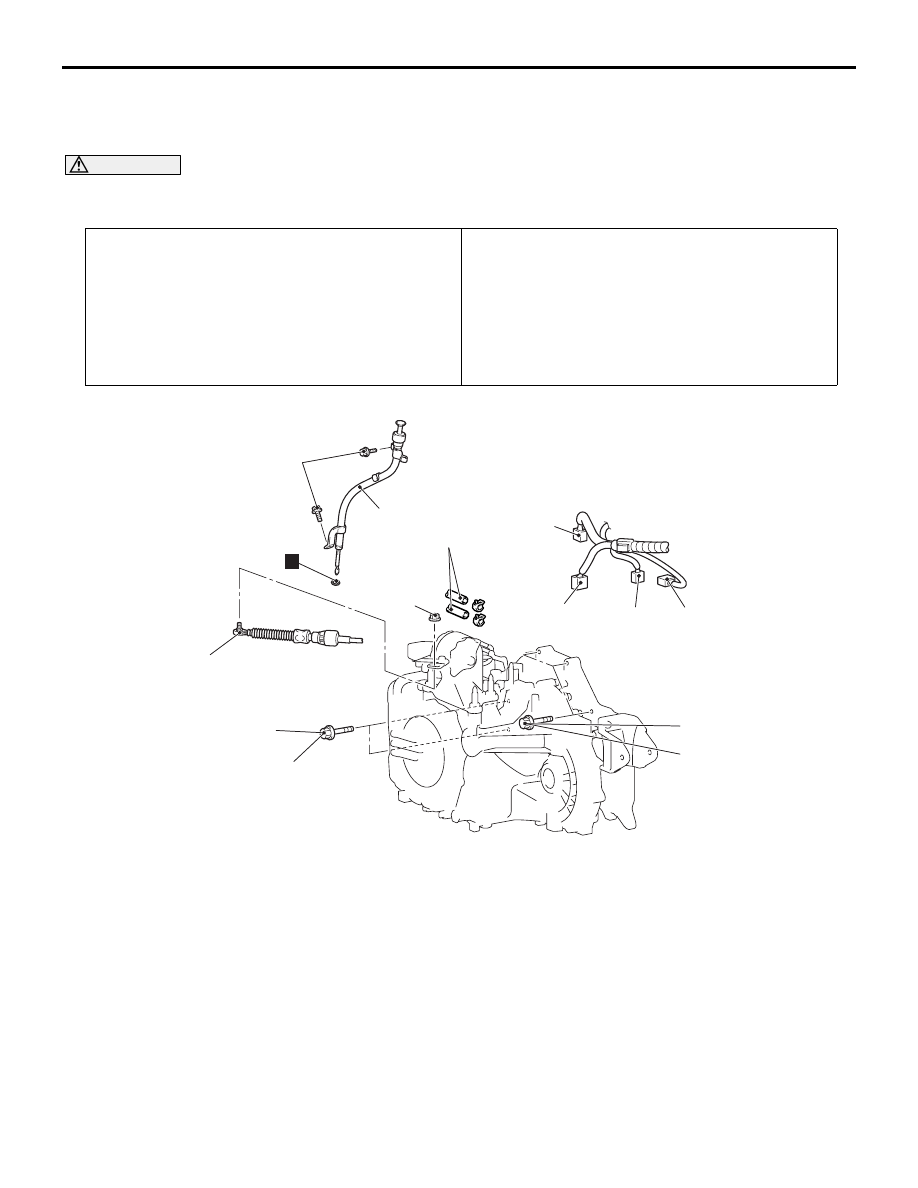
REMOVAL AND INSTALLATION

M1231005700608

CAUTION

*

: Indicates parts which should be temporarily tightened, and then fully tightened after placing the 

vehicle on the earth and loading the full weight of the engine on the vehicle body.

Pre-removal Operation
• Under Cover Removal 

• A/T Fluid Draining (Refer to 

P.23A-126

.)

• Air Cleaner Body Assembly, Air cleaner Bracket, Air 

Intake Hose Removal (Refer to GROUP 15 

P.15-3

.)

• Battery and Battery Tray Removal.

Post-installation Operation
• Under Cover Installation 

• A/T Fluid Supplying (Refer to 

P.23A-126

.)

• Air Cleaner Assembly Installation (Refer to GROUP 15 

P.15-3

.)

• Battery and Battery Tray Installation.

• Selector Lever Operation Check (Refer to 

P.23A-139

.)

• Front Wheel Alignment Check and Adjustment (Refer to 

GROUP 33, On-vehicle Service 

P.33-4

.)

AC311484AB

1

50 ± 4 N·m

2

3

4

5

6

10

9

50 ± 4 N·m

12 ± 2 N·m

11 ± 1 N·m

7

N

8

Removal steps

>>D<<

1.

Transmission control cable

2.

A/T control solenoid valve 
assembly connector

3.

Inhibitor switch connector

4.

Input shaft speed sensor 
connector

5.

Output shaft speed sensor 
connector

6.

Oil filler tube

7.

O ring

8.

A/T fluid cooler hose 
(Transmission side)

Radiator lower hose clamp

9.

Starter motor installation bolt

<<A>>

>>C<<

10. Transmission upper connecting 

bolts

Removal steps (Continued)

TRANSMISSION ASSEMBLY

AUTOMATIC TRANSMISSION (FF)

23A-148

REMOVAL SERVICE POINTS
<<A>> TRANSMISSION UPPER 
CONNECTING BOLTS

Do not fully unscrew the bolts from the transmission 
assembly. Only loosen the bolts.

<<B>> TORQUE CONVERTER AND 
DRIVE PLATE COUPLING BOLTS 
REMOVAL

1. Turn the crank shaft so that it is positioned to 

allow the drive plate bolt to be unscrewed.

AC302948 AB

11

50 ± 4 N·m

12

22 ± 4 N·m

44 ± 10 N·m

13

15

16

9.0 ± 1.0 N·m

57 ± 7 N·m*

90 ± 10 N·m

20

21

21

22

23

24

57 ± 7 N·m

83 ± 12 N·m

N

N

14

17

18

19

N

49 ± 9 N·m

95 ± 15 N·m

83 ± 12 N·m*

50 ± 4 N·m

Removal steps

Drive shaft assembly (Refer to 
Group 26 

P.26-11

)

11. Transmission stay
12. Bell housing cover

Front Exhaust Pipe and Exhaust 
Pre-muffler Connection (Refer to 
GROUP 15, Exhaust Pipe and 
Main Muffler 

P.15-9

.)

<<B>>

13. Torque converter and drive plate 

coupling bolts

14. Self-locking nut 
15. Centermember
16. Selflocking nut 
17. Transmission case rear roll 

stopper bracket

18. Transmission mounting bracket 

pad

19. Self-locking nut 

<<C>>

20. Transmission mounting bracket 

assembly

>>B<<

21. Transmission mounting stopper
22. Transmission mounting body side 

bracket

Support the transmission 
assembly with a transmission 
jack.

23. Transmission lower connecting 

bolts

>>A<<

24. Transmission assembly

Removal steps (Continued)

TRANSMISSION ASSEMBLY

AUTOMATIC TRANSMISSION (FF)

23A-149

2. Push in the torque converter into the transmission 

side and make a point to ensure that the torque 
converter does not remain on the engine side.

<<C>> TRANSMISSION MOUNT 
BRACKET ASSEMBLY REMOVAL

1. Use a garage jack to support the engine and 

transmission assembly. Remove the transmission 
mounting bracket and then set the engine hanger 
(special tool MB991895 or MB991928).

2. <Engine hanger (special tool MB991928) is used>

(1) Assemble special tool MB991928. (Set the 

components below to the base hanger.)

• Slide bracket (HI)

• Special tool MB991931: Joint (140) × 2

• Special tool MB991932: Foot (standard) × 2

(2) Set the foot (standard) MB991932 of 

assembled special tool MB991928 to the front 
fender assembling bolts as shown.<rear said>

(3) Set the joint (140) MB991931and foot 

(standard)  MB991932 of assembled special 
tool MB991928 to the front end upper bar 
assembling bolts as shown.

NOTE: Slide the slide bracket (HI) to balance 
the engine hanger.

(4)  Hook the chains of special tools MB991527 

and MB991454 to support the engine and 
transmission assembly. Remove the garage 
jack and then remove the transmission 
assembly upper fixing bolts.

3. <Engine hanger (special tool MB991895) is used>

(1) Set a special tool MB991895.

(2) Set the rear foot of special tool MB991895 to 

the front fender assembling bolts as shown.

(3) Set the front foot of special tool MB991895 to 

the front end upper bar assembling bolts as 
shown.

NOTE: Slide the front foot of special tool 
MB991895 to balance the engine hanger.

(4) Hook the chains of special tools MB991527 

and MB991454 to support the engine and 
transmission assembly. Remove the garage 
jack and then remove the transmission 
assembly upper fixing bolts.

INSTALLATION SERVICE POINTS
>>A<< TRANSMISSION ASSEMBLY 
INSTALLATION

AC301806

MB991932

MB991931

MB991932

AC

AC301803

MB991454

MB991527

MB991928

AC

AC301807AC

MB991895

AC301804

MB991454

MB991527

MB991895

AC

AC209056

Approximately
12.2 mm

AE

Torque converter

TRANSMISSION ASSEMBLY

AUTOMATIC TRANSMISSION (FF)

23A-150

Engage the torque converter into the transmission 
side securely, and then assemble the transmission 
assembly on the engine.

>>B<< TRANSMISSION MOUNT 
STOPPER INSTALLATION

Install the transmission mount stopper so that the 
arrow mark points as shown in the illustration.

AC303910

Transmission
mounting
stopper

Transmission
mounting
body side
bracket

: Engine side

AC


Content   ..  868  869  870  871   ..