Mitsubishi Grandis. Manual - part 845


  Index      Mitsubishi     Mitsubishi Grandis - service repair manual


Search            


Content   ..  843  844  845  846   ..


Mitsubishi Grandis. Manual - part 845


TROUBLESHOOTING <A/T>

AUTOMATIC TRANSMISSION (FF)

23A-47

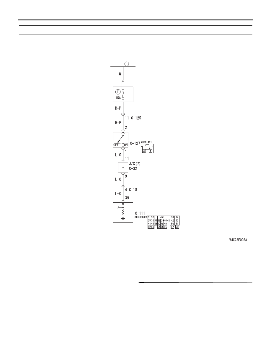
Code No.26: Stop lamp switch system

OPERATION

The stop lamp switch judges whether the brake 
pedal is depressed or released, and sends the 
information to the engine-A/T-ECU.

DIAGNOSIS CODE SET CONDITIONS

If the stop lamp remains on for consecutively five 
minutes or more while the vehicle is being driven or 
all the stop lamp bulbs are blown, it is judged that 
there is a short or open circuit in the stop lamp switch 
and diagnosis code 26 is set.

POSSIBLE CAUSES

• Malfunction of brake pedal

• Malfunction of stop lamp switch

• Damaged harness wires and connectors

• Malfunction of the engine-A/T-ECU

DIAGNOSIS

STEP 1. Check that the stop lamps illuminate and 
extinguish normally.

The stop lamps should illuminate when the brake 
pedal is depressed, and extinguish when released.

Q: Is the check result normal?

YES : 

Go to Step 7.

NO : 

Go to Step 2.

Wire colour code
B : Black     LG : Light green
G : Green     L : Blue      
W : White     Y : Yellow
SB : Sky blue     BR : Brown 
O : Orange     GR : Gray  
R : Red     P : Pink     V : Violet       

FUSIBLE
LINK

RELAY
BOX

STOP LAMP
SWITCH

ENGINE-
A/T-ECU

26

Stop lamp switch system circuit

<LHD>

TROUBLESHOOTING <A/T>

AUTOMATIC TRANSMISSION (FF)

23A-48

STEP 2. Check the brake pedal height.

Refer to GROUP 35A 

− On-vehicle Service, Brake 

Pedal Check and Adjustment (Refer to 

P.35A-4

).

Q: Is the check result normal?

YES : 

Go to Step 3.

NO : 

Adjust the brake pedal height.

STEP 3. Check the stop lamp switch.

Refer to GROUP 35A 

− Brake Pedal and Stop Lamp 

Switch Continuity Check (Refer to 

P.35A-13

).

Q: Is the check result normal?

YES : 

Go to Step 4.

NO : 

Replace the stop lamp switch.

STEP 4. MUT-III data list

Item 26: Stop lamp switch (Refer to data list 
reference table 

P.23A-117

).

Q: Is the check result normal?

YES : 

Intermittent malfunction (Refer to GROUP 

00 

− How to Cope with Intermittent 

Malfunction 

P.00-5

).

NO : 

Go to Step 5.

STEP 5. Connector check: C-127 stop lamp 
switch connector

Check for the contact with terminals.

Q: Is the check result normal?

YES : 

Go to Step 6.

NO : 

Repair the defective connector.

STEP 6. Measure the voltage at stop lamp switch 
connector C-127.

Disconnect the connector, and measure the voltage 
between terminal No.2 and earth at the harness side.

OK: System voltage

Q: Is the check result normal?

YES : 

Go to Step 7.

NO : 

Go to Step 12.

STEP 7. Measure the voltage at engine-A/T-ECU 
connector C-111.
(1) Connect stop lamp switch connector C-127.

(2) Measure the voltage between engine-A/T-ECU 

connector C-111 terminal No.39 and earth.

OK:

Brake pedal depressed: System voltage
Brake pedal not depressed: 1 V or less

Q: Is the check result normal?

YES : 

Go to Step 8.

NO : 

Go to Step 10.

AC309520AD

Connector: C-127

Harness side

Brake pedal

4

3

2

1

AC309520AD

Connector: C-127

Harness side

Brake pedal

4

3

2

1

AC311284AH

Connector: C-111 <LHD>

Connector: C-111 <RHD>

Harness side

Engine-A/T-ECU

C-111 (GR)

C-111 (GR)

45

52

35

42 41

43
51

58

50

57

33

34

36

403938 37

47

55

48

56

44

49

46

54

3231

53

Engine-A/T-ECU

TROUBLESHOOTING <A/T>

AUTOMATIC TRANSMISSION (FF)

23A-49

STEP 8. Connector check: C-111 engine-A/T-ECU 
connector

Check for the contact with terminals.

Q: Is the check result normal?

YES : 

Go to Step 9.

NO : 

Repair the defective connector.

STEP 9. MUT-III data list

Item 26: Stop lamp switch (Refer to data list 
reference table 

P.23A-117

).

Q: Is the check result normal?

YES : 

Intermittent malfunction (Refer to GROUP 

00 

− How to Cope with Intermittent 

Malfunction 

P.00-5

).

NO : 

Replace the engine-A/T-ECU.

AC311284AH

Connector: C-111 <LHD>

Connector: C-111 <RHD>

Harness side

Engine-A/T-ECU

C-111 (GR)

C-111 (GR)

45

52

35

42 41

43
51

58

50

57

33

34

36

403938 37

47

55

48

56

44

49

46

54

3231

53

Engine-A/T-ECU

TROUBLESHOOTING <A/T>

AUTOMATIC TRANSMISSION (FF)

23A-50

STEP 10. Connectors check: C-18 intermediate 
connector, C-111 engine-A/T-ECU connector, 
C-32 J/C (7) <LHD>

AC310615

AQ

Connector: C-18
<LHD>

C-18

2

6

1

5

9

3

7 8

10

4

AC310628

C-18

AC310628AT

Connector: C-18
<RHD>

C-18

2

6

1

5

9

3

7 8

10

4

AC311284AH

Connector: C-111 <LHD>

Connector: C-111 <RHD>

Harness side

Engine-A/T-ECU

C-111 (GR)

C-111 (GR)

45

52

35

42 41

43
51

58

50

57

33

34

36

403938 37

47

55

48

56

44

49

46

54

3231

53

Engine-A/T-ECU

AC310613

AY

Connector: C-32 <LHD>

C-32

23

12

1

7

29

18

4

26

15

1314

25

24

2 3

1617

28

27

5 6

10

32

21

1920
3031

8 9

22
33

11


Content   ..  843  844  845  846   ..